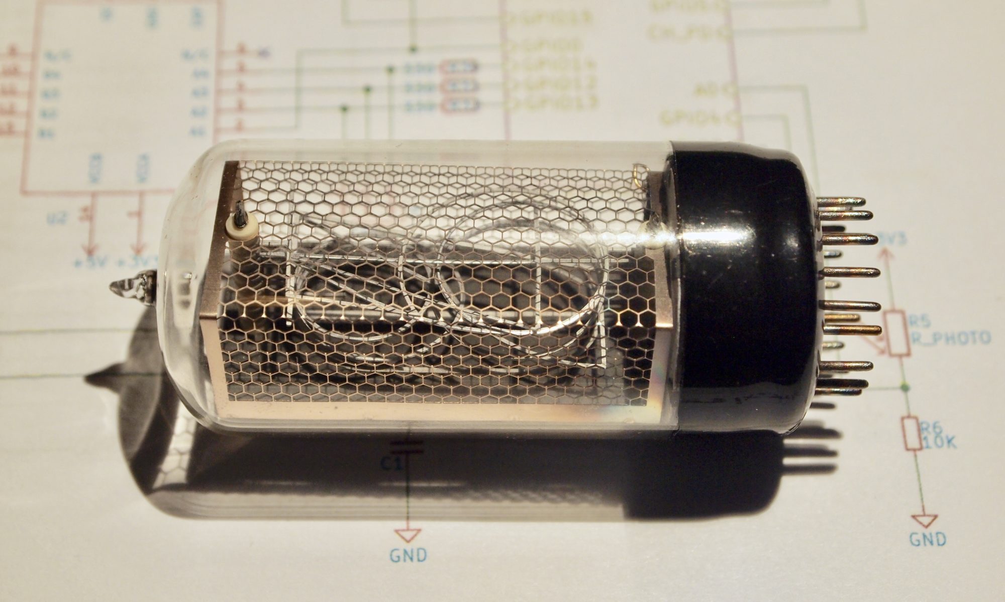
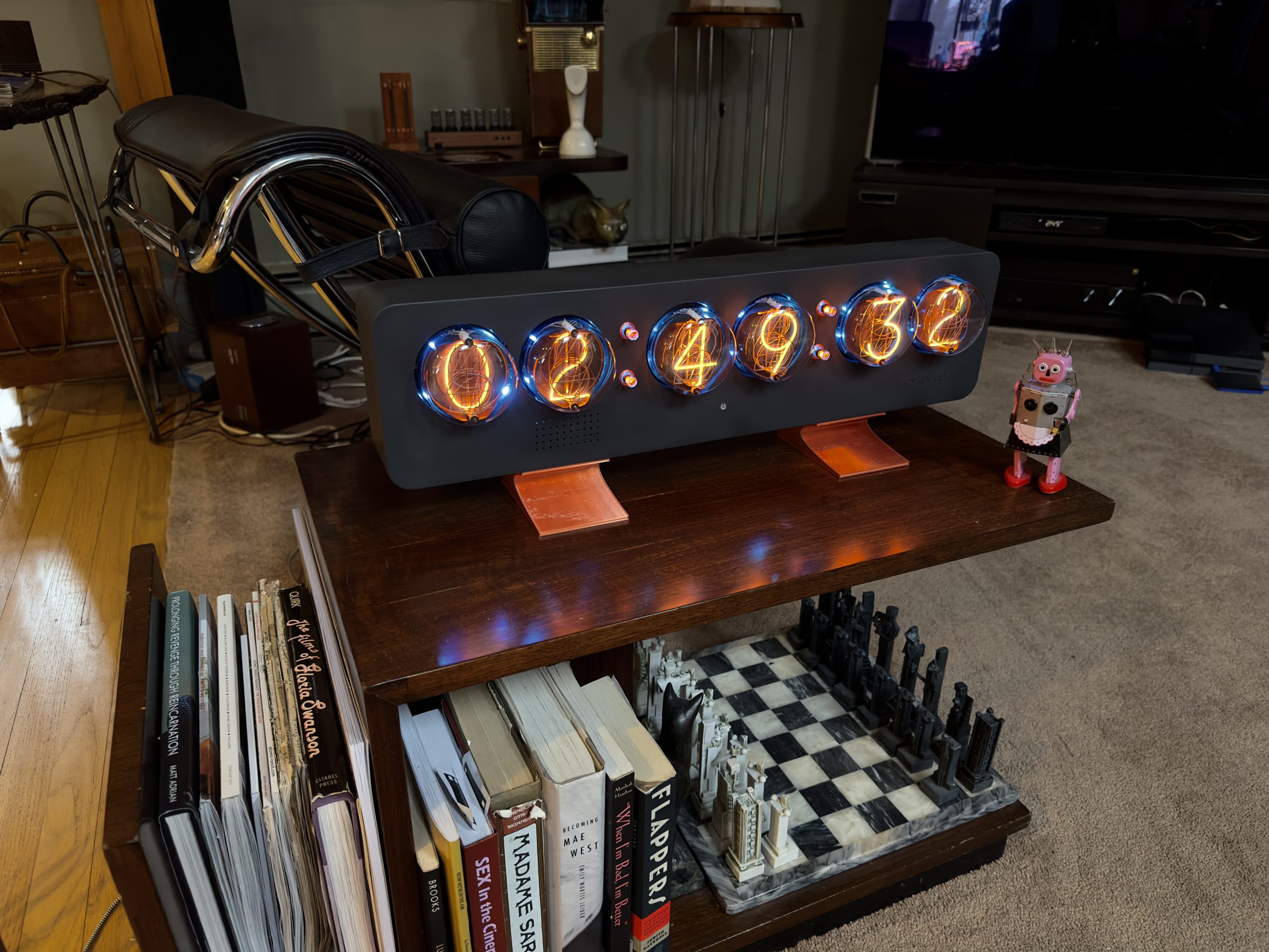
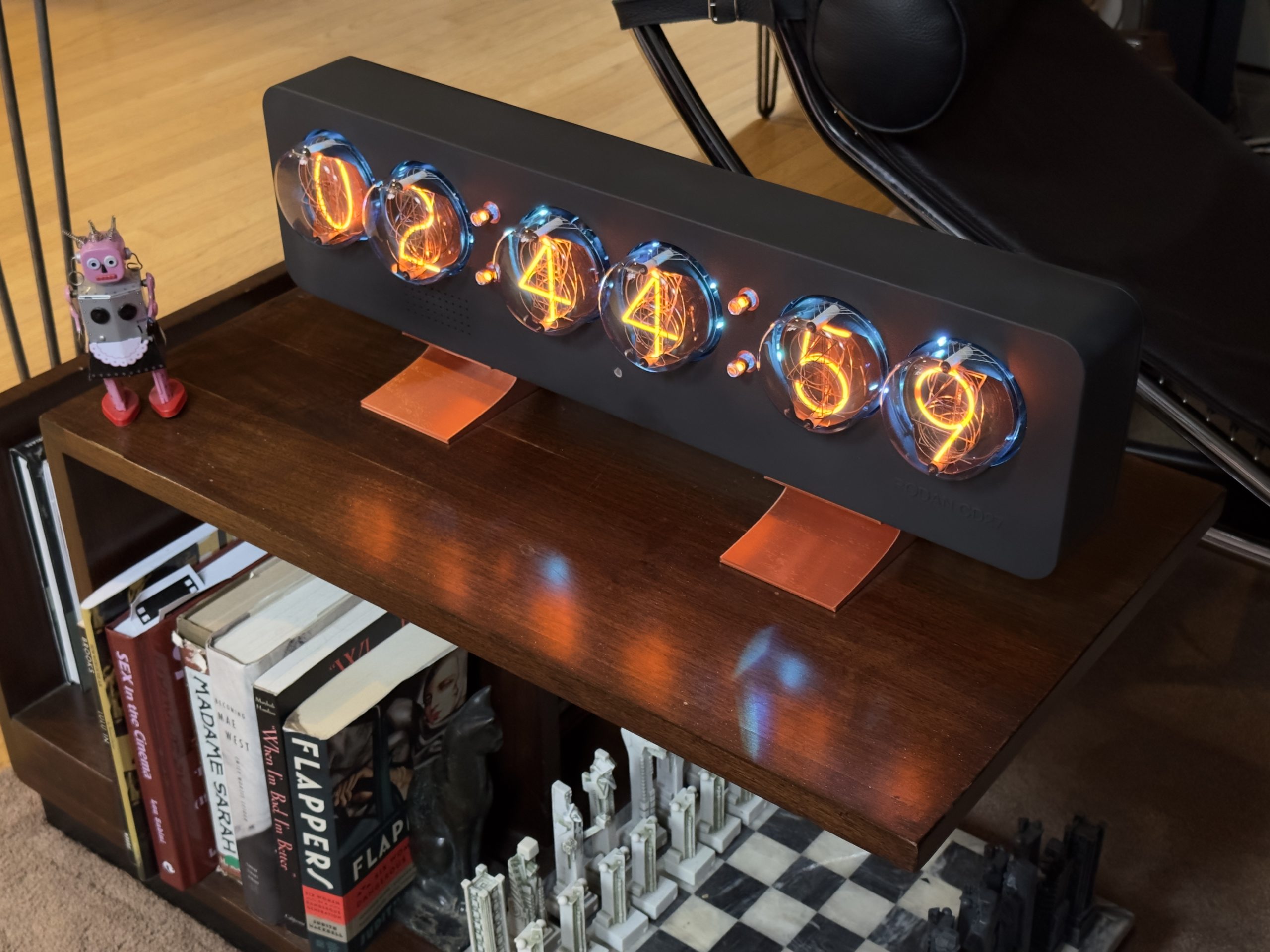
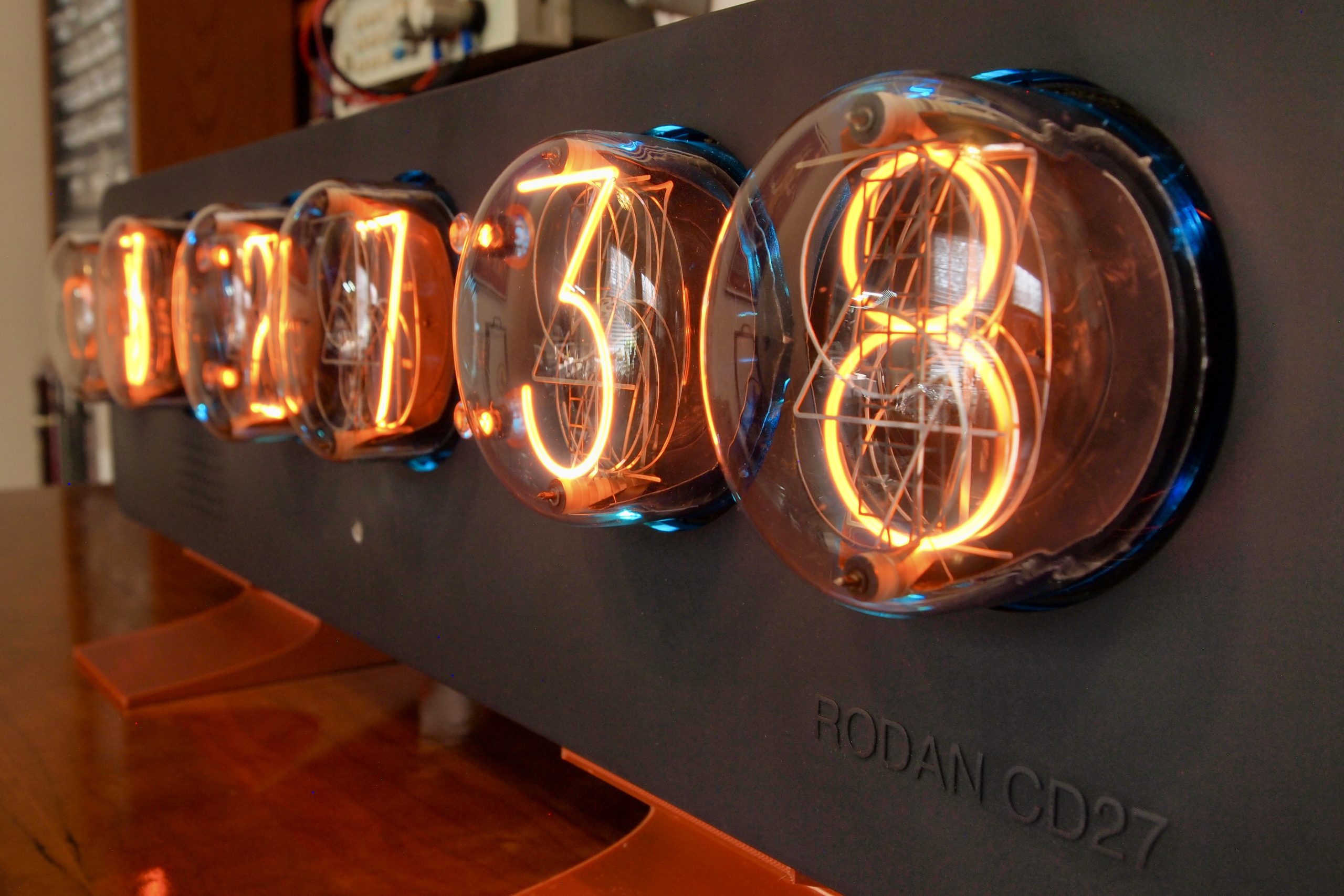
A few years ago I was lucky enough to win an auction for a set of Rodan CD27 nixie tubes. These are the largest end-view nixie tubes ever made and were used for displays in the Japanese bullet train and at the Tanegashima space center. These were used tubes, though with only minor cosmetic blemishes, and a little coaxing had them functioning properly. Recently I figured out how I might create a nixie clock to show these off, so I set about putting it all together.
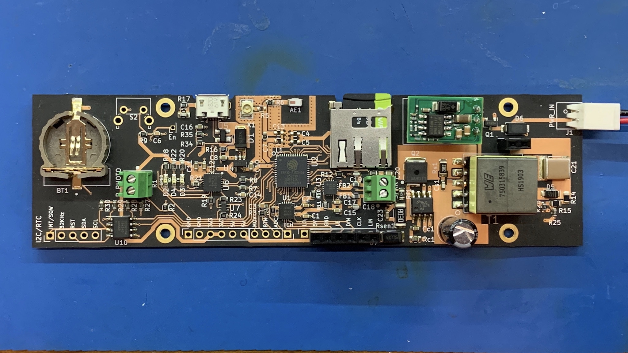
The basic idea was to use a spare board that I had remaining from an order when I developed my large-tube nixie clock. That clock used a two-board design – a main board and a display board – that I have used in several clocks since then. The main board uses an ESP32 Pico as the CPU and includes a USB interface, an HV power unit, an SD card reader, a mono amplifier and an RTC chip.
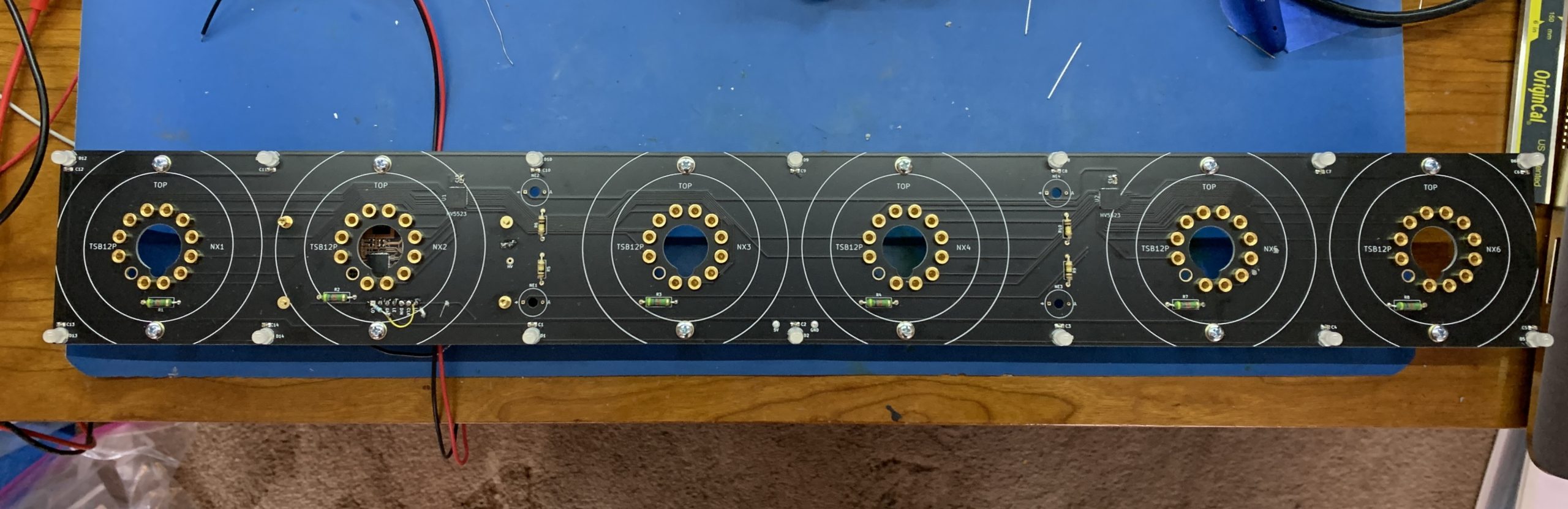
So the next step was to develop the display board. The only real difference between this display board and others I have designed, that use the same stack-up, is the size. This size was only an issue for soldering the QFN display controllers I use. I would normally use my reflow oven for this, but this board was way too large at 530mm long, so I had to use the heat gun on my re-work station to do that.
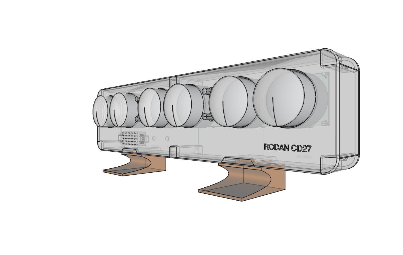
The next step was to design the case. I use FreeCAD for my 3D design work and KiCAD for my PCB design. I could use a FreeCAD plugin (stepup) to import a 3D model of the KiCAD boards into FreeCAD, and another plugin (assembly4) to produce a combined view of all of the parts of the clock, including the case, the electronics and other components. I had to create models for some of them, such as the nixie tubes and the speaker, but it allowed me to check that everything would fit together properly once they were manufactured. This is a render of a complete assembly. You can see I used transparency to allow me to see how everything was fitting together:
I’d figured out that I would 3D print it, but at around 600mm wide, the case is bigger than most hobby printers can print, so I either had to slice it up in to smaller pieces, or have it manufactured. I new that JLCPCB offered a printing service, so I uploaded early files to see what options I had. The cheapest option for a model this size was SLA printing – aka resin printing. FDM printing wasn’t available. I had no idea how printable this design was using SLA, but I followed their guidelines as well as I could. I also had to re-think how I would fasten everything together – I had been planning to use brass inserts to accept M3 screws, but that wouldn’t really work for resin. Instead I designed pockets into the structure that would accept M3 nuts that I could glue in place, and in to which the screws would fit.
Fortunately it all worked out very well. I chose a hard black resin and the finish was a lot better than I could achieve on my own printers, with much better tolerances. The only issue was some minor warping on the long edges, which was un-noticeable when the two halves were screwed together.
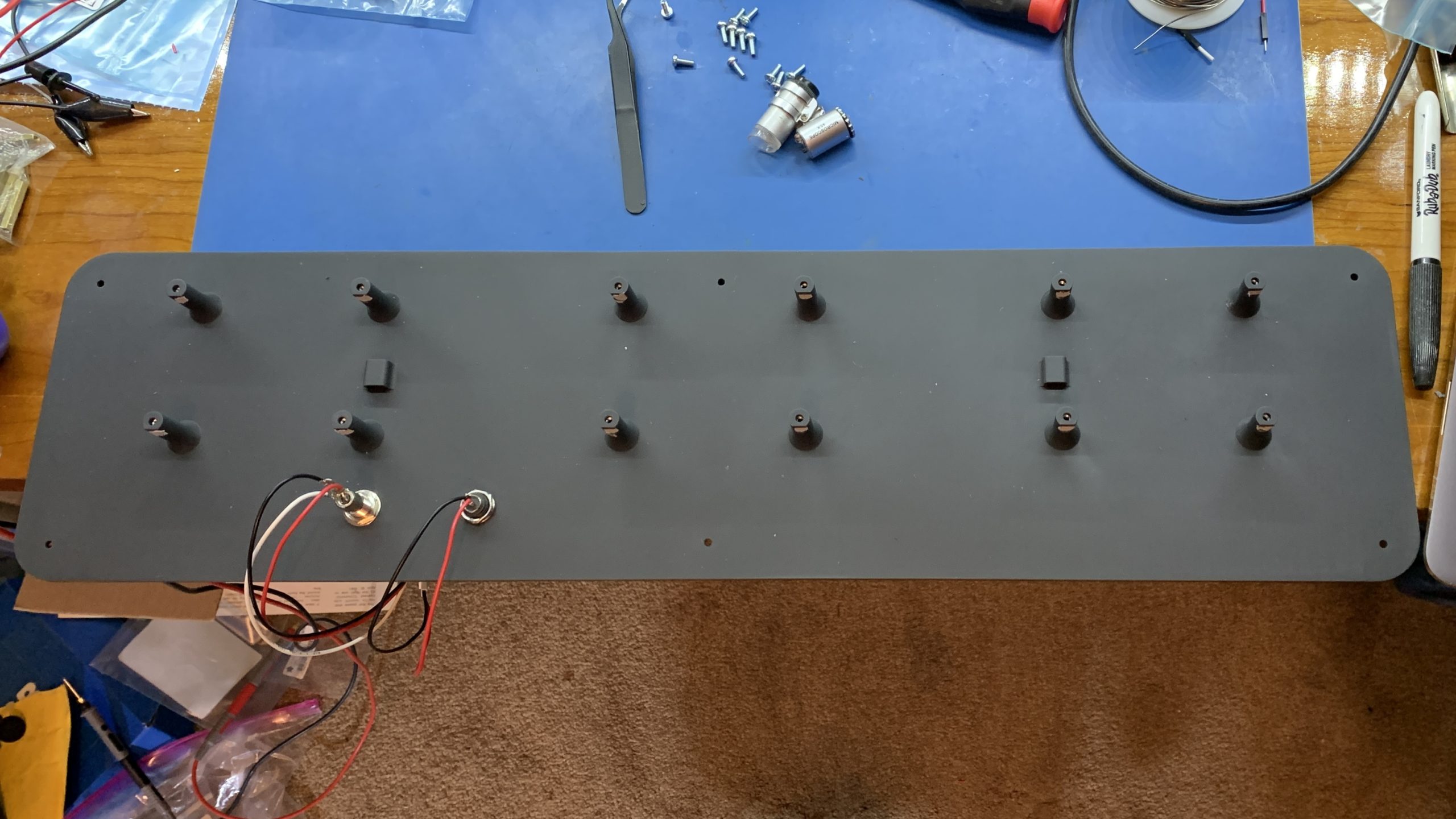
Below you can see the inside of the back of the case showing the support columns for the display board and the fitted power socket and a movement sensor socket. If you enlarge the image you can see that every column has a pocket inside which is an M3 nut.
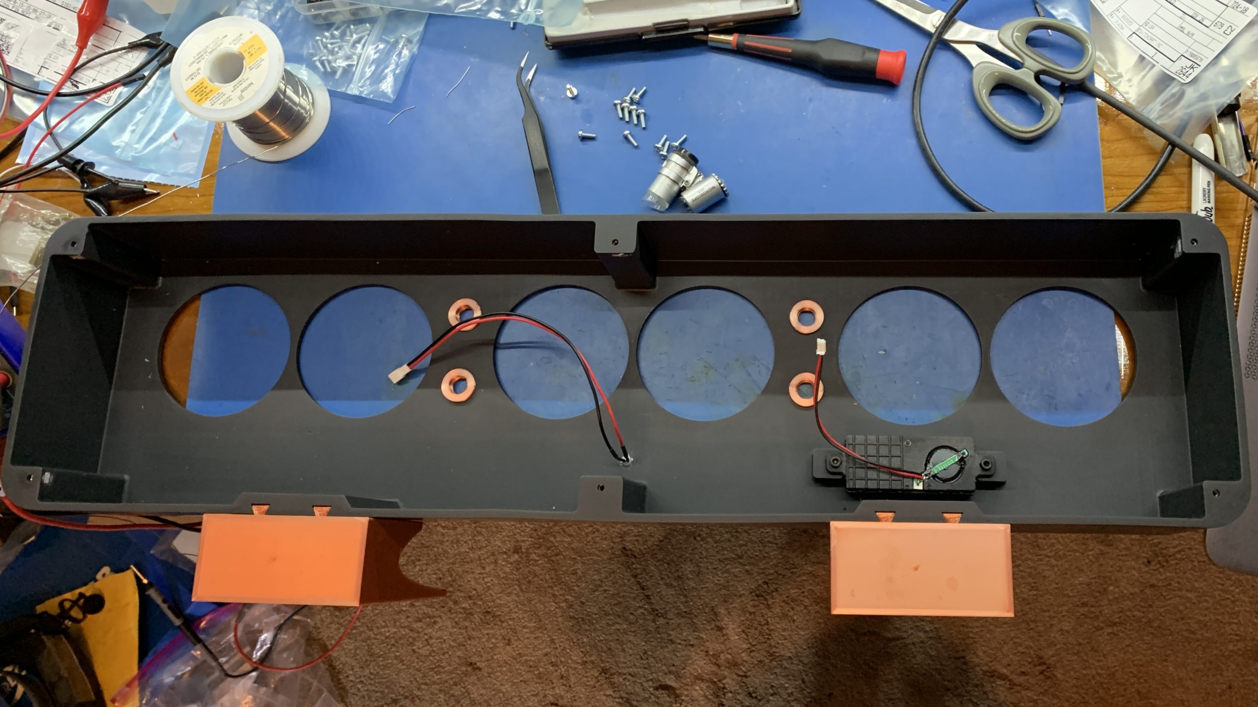
This next image shows the inside of the front side of the case. You can see the speaker and light sensor are mounted and there are also some feet I printed on my own printer in copper silk PLA – the case is designed to be either free-standing or hung on a wall, so the feet are optional.
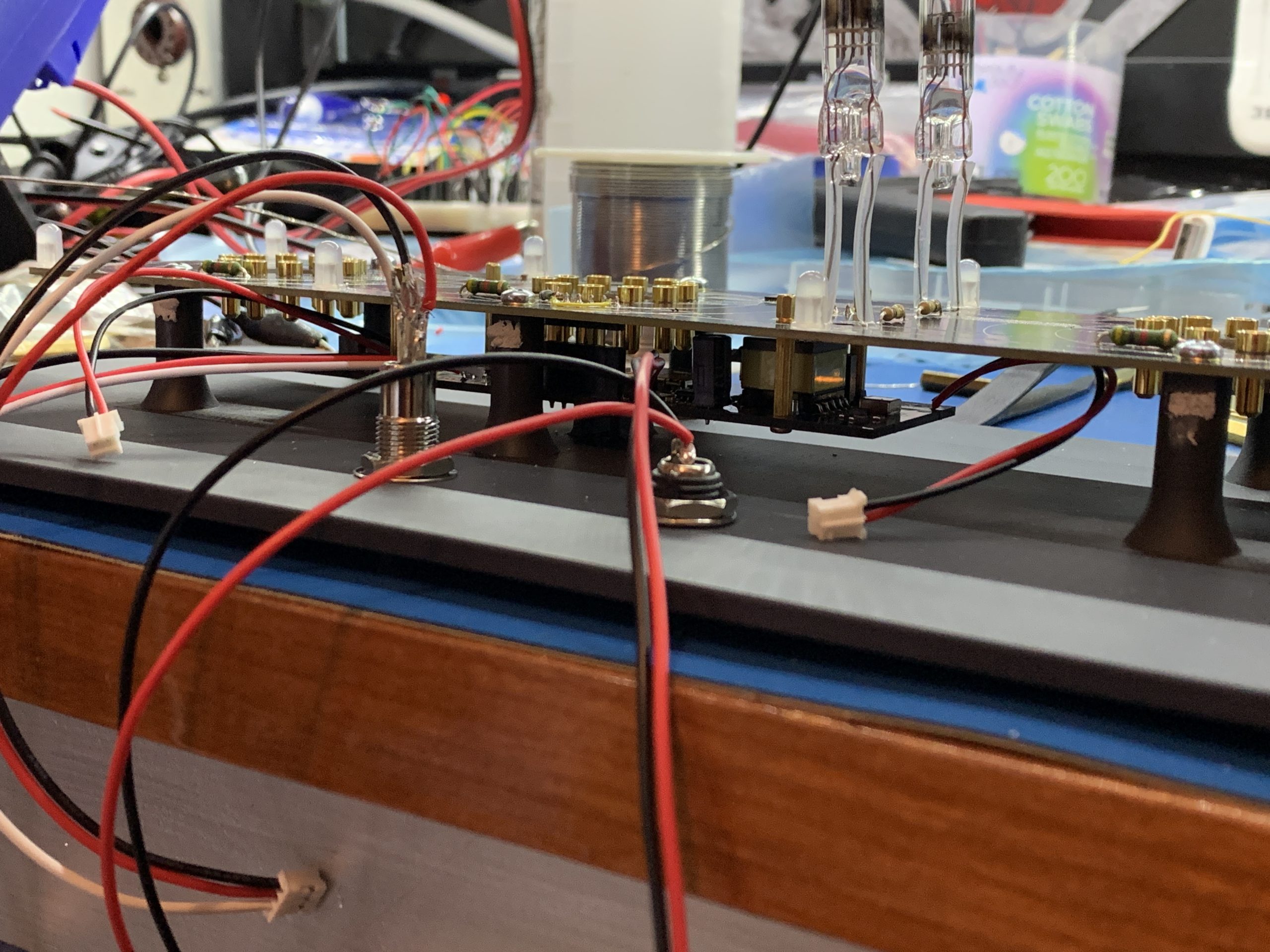
The next photo shows the electronics mounted to the case.

This is a closeup where you can see how the main board is mounted below the display board, by which it is dwarfed.
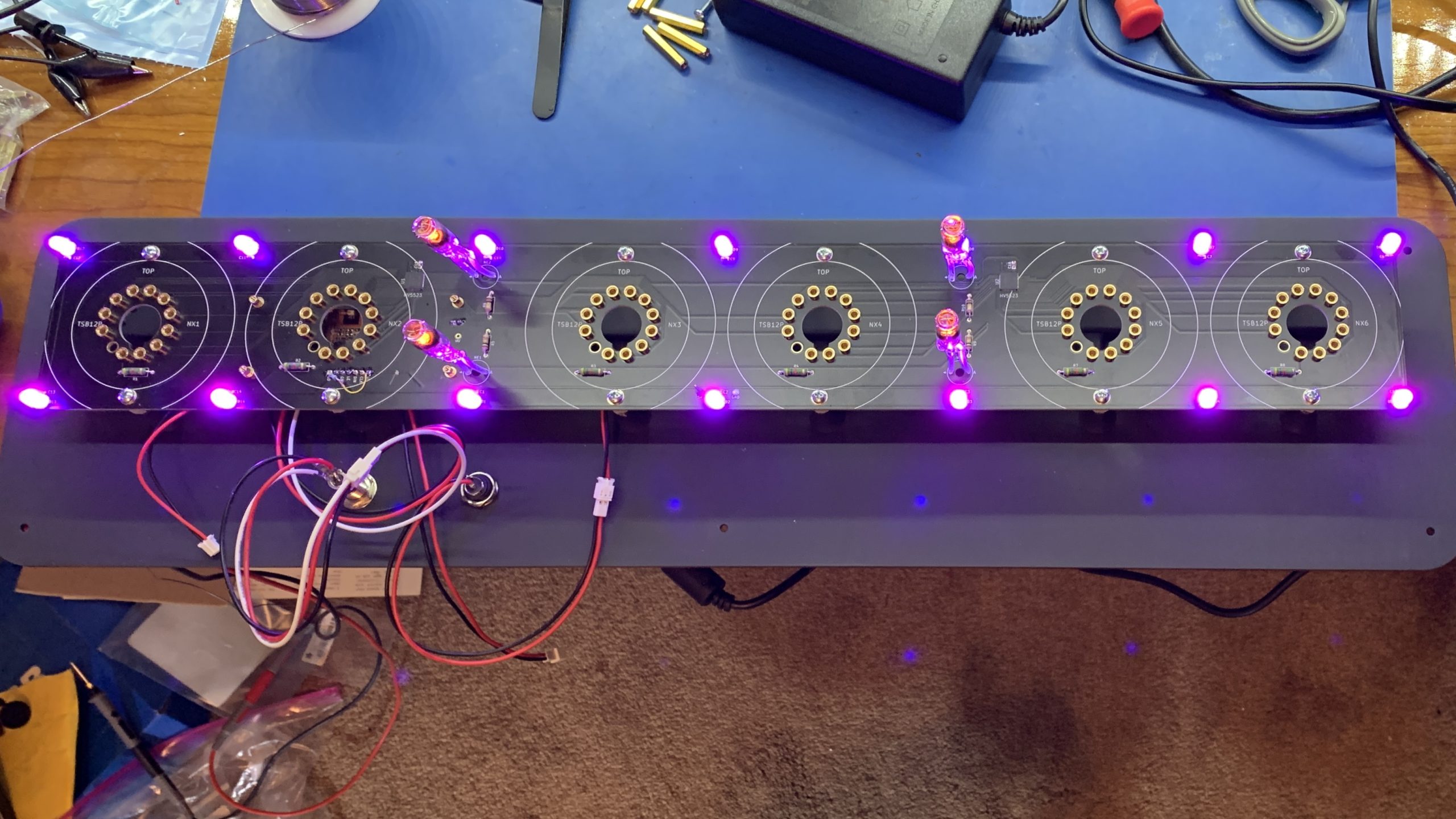
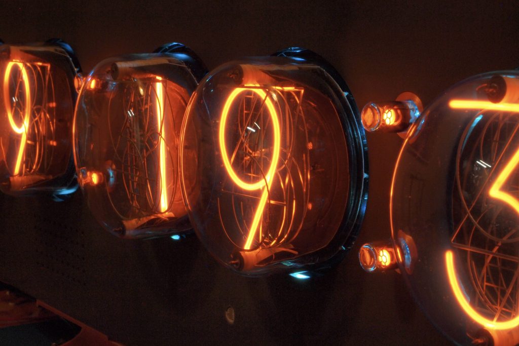
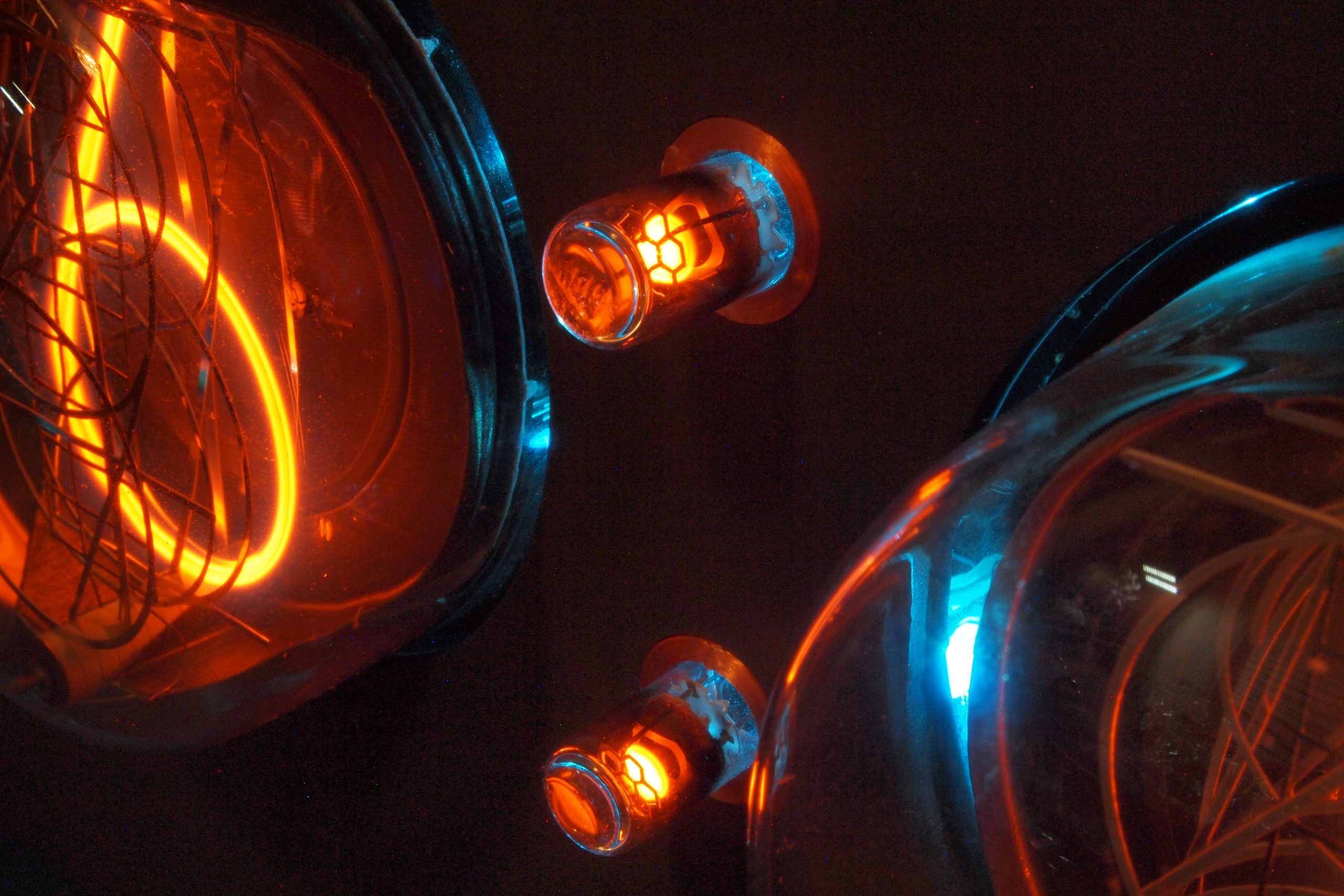
A quick power test to check everything is wired up correctly. BTW the colons are soviet TNI-1.5D nixie tubes.
The software for the clock is basically the same as for all my other clocks that use the ESP32, with some minor differences because of part substitutions I had to make, so it includes NTP time sync, auto daylight-savings, a web-based configuration GUI, OTA software updates, auto-dimming and configurable sounds. The sounds include ticks, chimes, strikes and alarms. The sounds caused me some worries at first as some of them were distorted. I eventually discovered that they hadn’t copied properly to the SD card I was using. In the process I discovered a neat little embedded FTP server that would run on the ESP32 – SimpleFTPServer, which allowed me to upload the new files to the SD card without taking the clock apart (the OTA update feature also meant I didn’t have to take it apart to upload the new firmware that included the FTP server).
I’ll finished with some shots of the completed clock.
Great work, Paul!
That is one amazing clock.
Beautiful!
Looks Fantastic.Just gave a couple off Roden’s,too a freind.Glad the Socket came in the box…Lovely tubes.