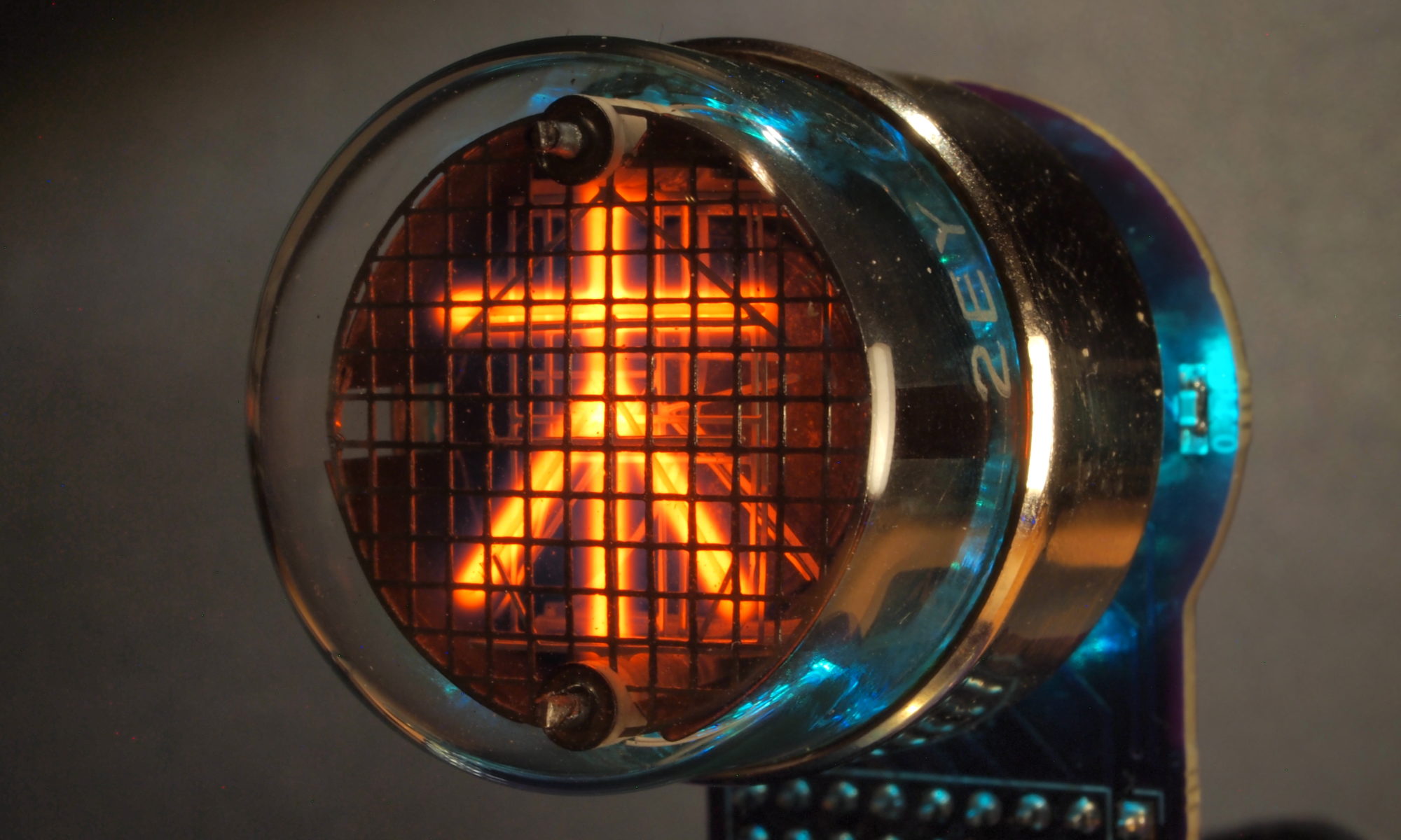
ITS1A Clock
I didn’t think that my first six tube clock would be an ITS1A clock, but after I got some of the tubes and spent a little time getting them to light up (and then be able to control what was displayed), it seemed a small step to building an actual clock.

Guiding Principles
- I wanted this to be all through-hole components so that I could sell spare boards as kits for others to build.
- I wanted to re-use a lot of my existing clock code that runs on ESP8266 chips.
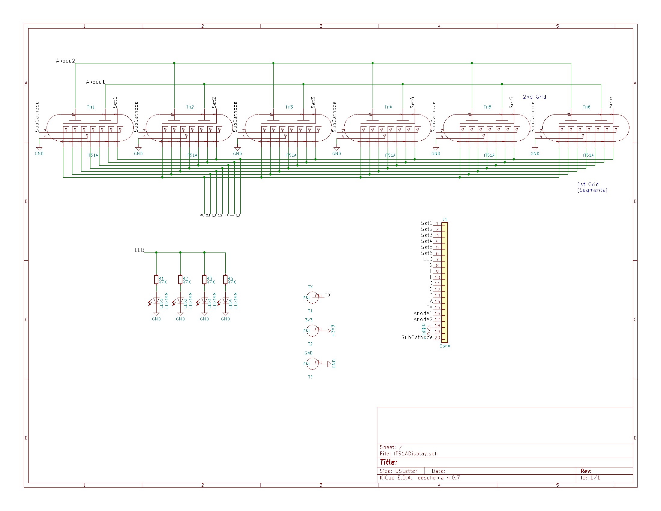
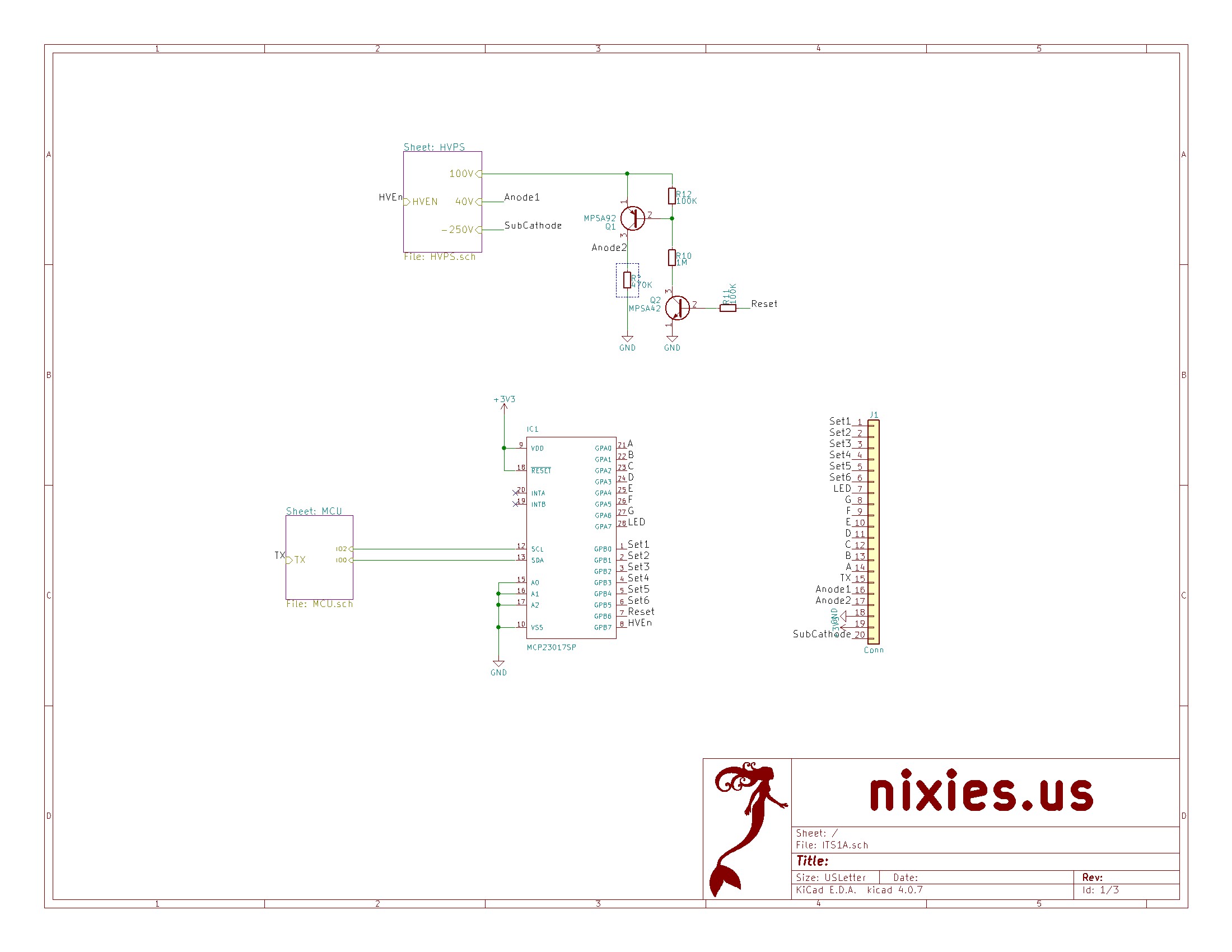
Control Circuitry
The control circuitry is documented here. Rather than go into all the same details, I’ll just summarize here:
- The sub-cathode (the -250V line, pin 7) is held constant.
- The 1st anode (40V, pin 2) and the 2nd anode (100V, pin 14) are normally held high, and are briefly pulled low to reset the thyratron – i.e. to make it possible to change the state of a segment. The datasheet states a shortest duration of this pulse of 500μs. In practice some tubes were reluctant to clear with this timing, so I made it configurable up to 5,000μS.
- The desired state of the segments (1st grid) is then set: 0V = on, above 0.4V = off.
- The state is locked in by briefly pulling the 2nd grid (pin 6) high (normally it is at 0V). Again the datasheet specifies a minimum of 100μs. I made this configurable too, up to 1,000μs.
- The display is multiplexed. This is achieved by only pulsing the 2nd grid on the tube whose display should change.
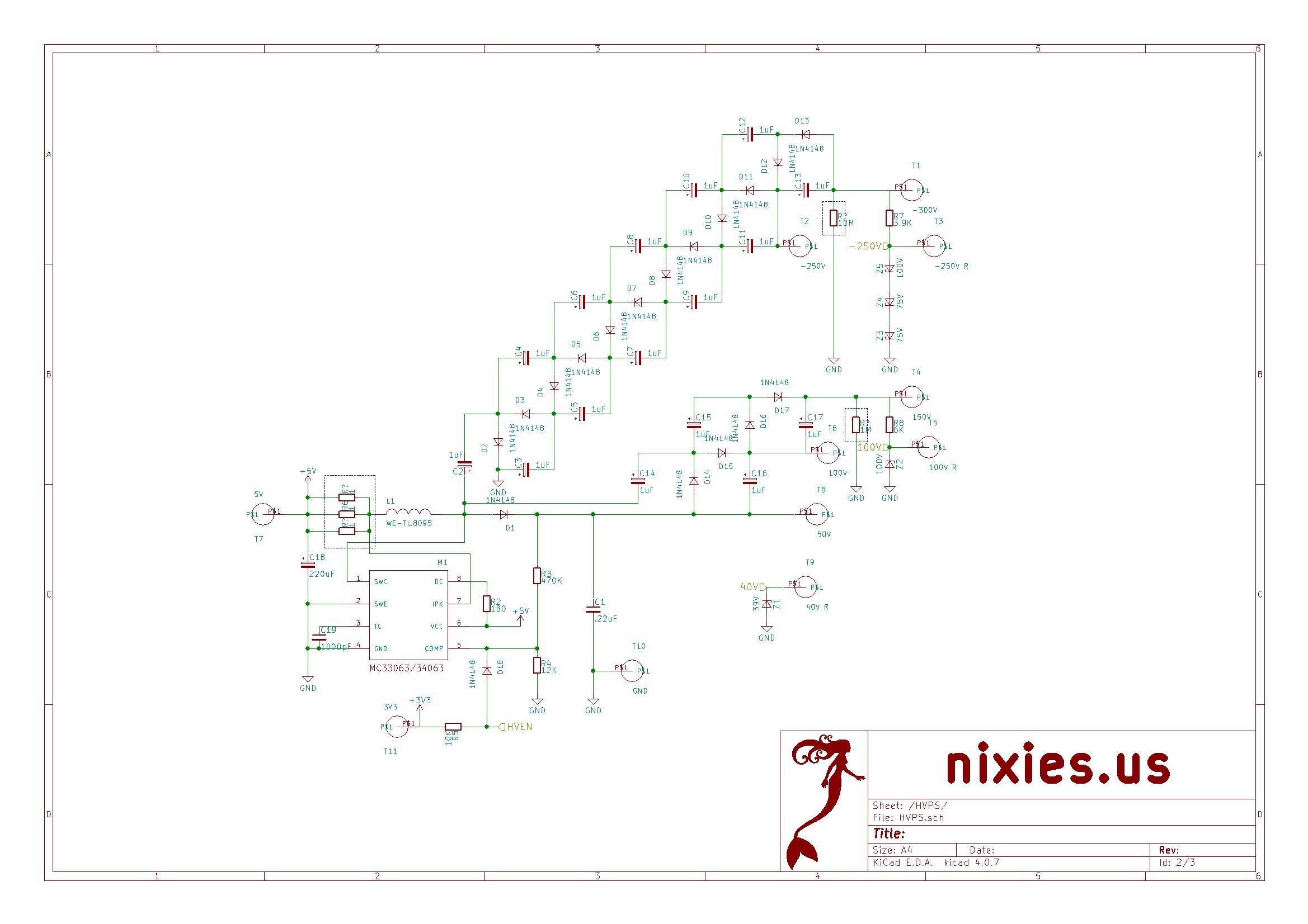
Power Supply
The core of the power supply is a boost converter based around the MC33063. This is configured to produce roughly 50V. The unrectified output is then fed into a couple of Cockroft-Walton ladders to produce the 100V and -250V.
Life isn’t that simple, of course. Cockroft-Walton ladders are leaky, and the MC33063 can’t really produce 50V at the power levels I need. So the ladders actually go up to a nominal 150V and -300V, then Zener voltage clamps set the 100V and -250V. An interesting thing to note is the tolerance on the zener voltage. Typically this is ±5%, which is ±12.5V for the -250V level. This is a little extreme, so I managed to find some with a tolerance of ±2%.
The 40V is produced by a Zener clamp, which relies on the characteristics of the ITS1A/B tube for this pin.
Finally(?), I added some bleeder resistors to drain all those capacitors when the power is removed. These are very high voltages that can give quite a jolt. Without the bleeder resistors, it takes a couple of minutes for them to decay to around 20V.
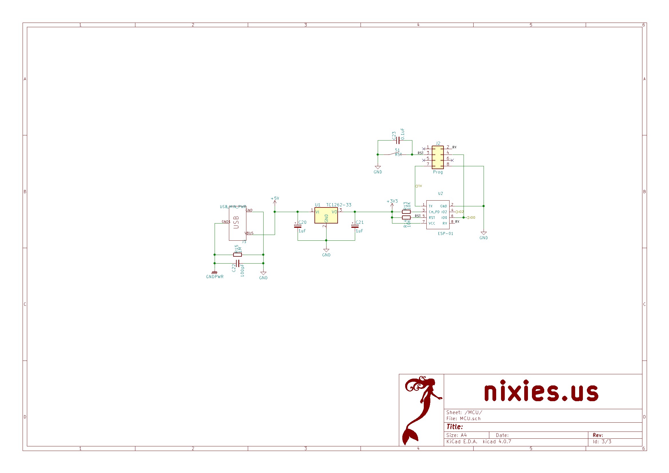
Logic-Level Components
The ITS1A/B are actually very easy to drive – by design they can be directly controlled using logic-level signals. I was somewhat limited by my self-imposed requirements – an ESP8266 and only through hole. The only off-the-shelf product that met these requirements was the ESP-01. This exposes a bare minimum of GPIO pins, but as I fleshed out how many control pins I needed, it became clear that the ESP8266 just doesn’t have enough anyway. So I settled on using a MCP23017 I/O expander. It has 16 GPIO, can be controlled using I2C and works at 3V3.
Software
The software makes use of the ESP8266 wifi connectivity to synchronize time with the internet and provide a web-based configuration dashboard. In fact, there is no RTC chip in the clock.
This web control dashboard uses JQuery mobile to provide a smart-phone-friendly interface to all of the configuration options. This is an example screen:
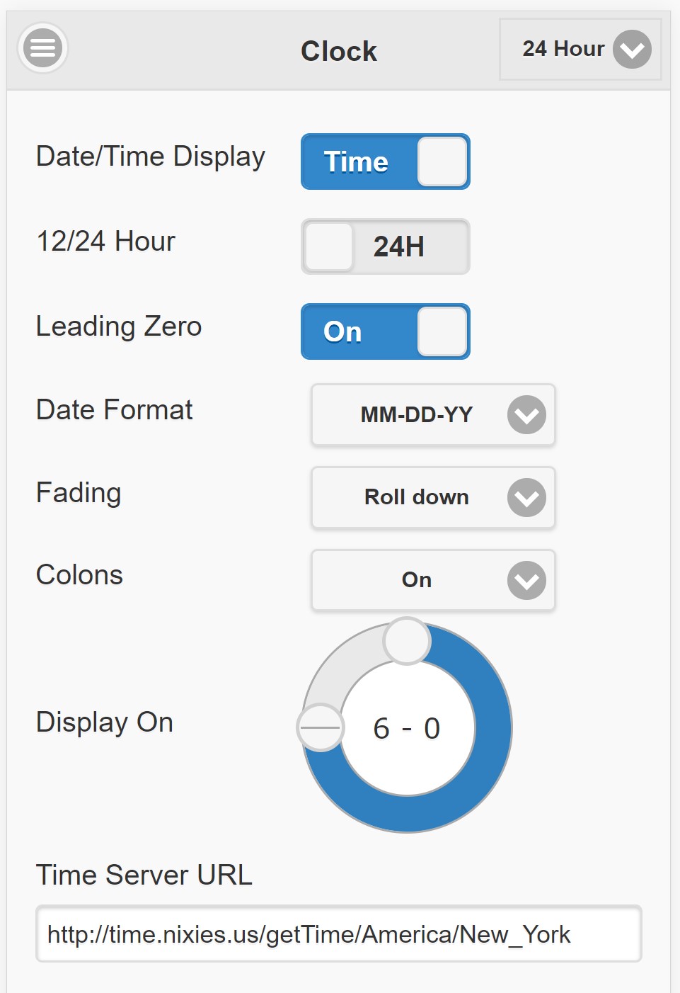
I used the ESP8266 Core for Arduino to program the ESP8266 – it comes with many great libraries that allow me to focus on developing the actual clock code.
The clock can also be controlled via Alexa – it uses the very simple FauxmoESP library. Did I mention that the Arduino platform has great library support already?
Video
Here is a video of it in action. You can see it has backlighting. It is a string of neopixels that were literally glued on the back of the display board. The software will drive them if they are there.
Support
Files
Sean McQuilling uploaded the boards to OSHPark:
thyratron clock I love the design and concept. Never thought i would really even be interested in ITS1A tubes. You have brought them to life in such a way i think they are fantastic. I would love to build one of these. Would you happen to have any of the boards and tubes to sell? I hope there is not a lot of programming involved as i am not really “that guy”. Some basic function led back light color changing capabilities some different ways the numbers present themselves and I am loving it.
I am out of boards at the moment, but if I get enough interest I will do another run. As for the tubes, you would have to get them off ebay.
There is no programming involved. I would provide the ESP01 fully programmed.
So just let me know your email address and I will add you to the list. Use the ‘Contact Me’ tab on the main page.
Hello, is there compiled firmware still available for this ITS1A clock or do you still have pre-programmed ESP01s available?
Thanks!
There is a link to the binaries at the end of the article.
Surprisingly, this is still one of my favorite clocks in a large nixie stable. The idea of a glass enclosed display tube that is controlled by low voltage logic levels is clever and your implementation of the digit transitions from top to bottom and vice versa are truly unique. The ability to separately control base lighting that is independent from the tube backlighting makes this clock really stand out.
Great job, Paul – and thanks for sharing!
I have several Nixie clocks at the moment and would like to add this ITS1A clock into my stable. Do you offer kits that I can order?
I’m not making any more kits. You would have to have some board made yourself using the links on this page. vanadiy on eBay was selling some completed clocks made from this design.
It’s unfortunate that you aren’t making any more kits. I’ve never had a PCB printed, do you have a service you recommend and what file do I send them to have it printed? I’m interested in making this and sourcing the parts my self. This is beautifully unique clock.
I added a link at the end of the article
Most people recommend JLCPCB. They are very cheap.
You basically upload the Gerber files (link above) and they make the PCB and ship it.
The file is: W161318ASR4_CAM-v0.2.zip
Then you can source the components from digikey and/or ebay, etc.
Or, I can sell you one. 🙂 (I’d have to check if I still have anymore boards as I might have only complete clocks.
Would it be much of a hassle to convert to json 6 or have you already updated your code?
What is json 6?
The code uses version 5, but the current version is 6.15.0 (Not compatible with each other.)
What protocol does the clock use to get the time, is it ntp? Is it possible to use a different server?
It is a simple HTTP get. The code for the server is here with a link to one other server https://github.com/judge2005/timeserver. The basic idea is to call a server that has an accurate time zone database.
Hello. I built your clock using the files you’re kind enough to share. Thank you for that! I’m having an issue with it though that’s odd. It seems segment a (the top horizontal segment) on all 6 tubes remains on at all times. Any idea what could cause it? I’m going to continue trouble shooting later.
Pin 21 of the MCP23017 is probably shorted to ground. This pin is directly connected to the same pin on every tube, so the short could be anywhere along that connection. Another alternative is that the chip is faulty, but that seems unlikely.
Thank you! I’ll have a closer look today.
Pete
Hello! You were correct. Pin 21 on the MCP23017 was indeed shorted to ground. It seems the board has a short somewhere under the solder mask in the trace between pin 21 and the connector header. I removed the MCP23017, its socket, and the connector header between the logic board and display board thinking maybe I had a solder bridge that wasn’t easily visible. After removing those components and checking resistance between the pin 21 pad and the ground pad the short remained. The board was also shorted between the pin 14 pad of the connector and the ground pad. I repaired it by bypassing the trace between pin 21 and pin 14 with a wire. I also compared this board to others that I had made. Of course the others tested okay. The one I decided to use had the short. Long story short the clock now operates as intended. Thank you again for your help and quick reply.
Pete
I have also build the clock, thanks for your excellent project. I recently have the problem that the clock is showing the year as 13 instead of 21. The time is displayed correctly and the year fault remains even if the date format is changed around dd-mm-yy or yy-mm-dd. I checked the netsite data being sent and there the date and time are both correct Any ideas?
Can you post a picture?
Sorry l can’t find anyway of uploading a picture here. Clock has been working perfectly for 6 months, so I am thinking maybe a bit has flipped in the flash. 21 displays fine in the time.
Are you on facebook? If so, join this group: https://www.facebook.com/groups/1846965478705447
BTW this is fixed. There is no need to update the clock, it was the time server.
Wonder if anyone is still experimenting with these clocks — I’ve had one running for about a year, but, I have it turning the HV/tubes off at night (to save tube life) – but lately, when it’s time for the tubes to come back on, they don’t. I’d say maybe 1-2 days a week they successfully come back on, otherwise they stay blank.
Either all tubes won’t light or they all will. No real inbetween.
I’ve tried messing with the HV pulse settings and the like, it doesn’t seem to change anything. The documentation doesn’t describe these settings either.
Anyone have any idea why the tubes will light sometimes and sometimes not? It seems at first this didn’t happen, but as time has gone on it’s gotten worse. I doubt it’s 6 dead/dying tubes as they all behave in unison.
You’re right, it seems unlikely. Have you checked the voltages at the test points? Test them when the clock comes back on, but is blank.
I would recommend you join the Facebook group if you are on there. It is easier to have conversations (edit: I see you have, post your problem there and I’ll get a conversation going).