My wife bought several IN-9 nixie tubes as an anniversary present, so this is a quick project to display sound levels on one of them. Quick to put together, but a lot of research on exactly how to do it.
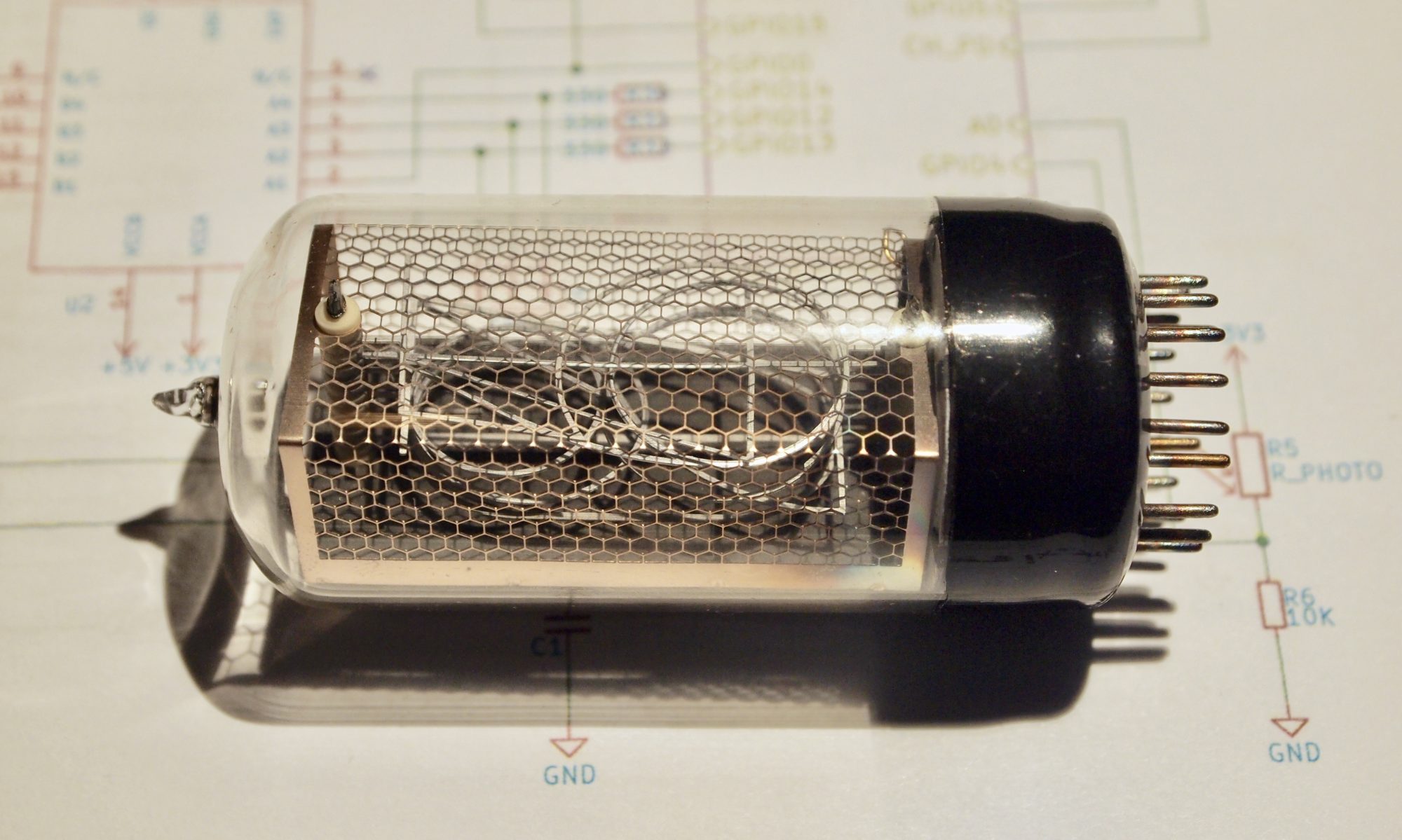
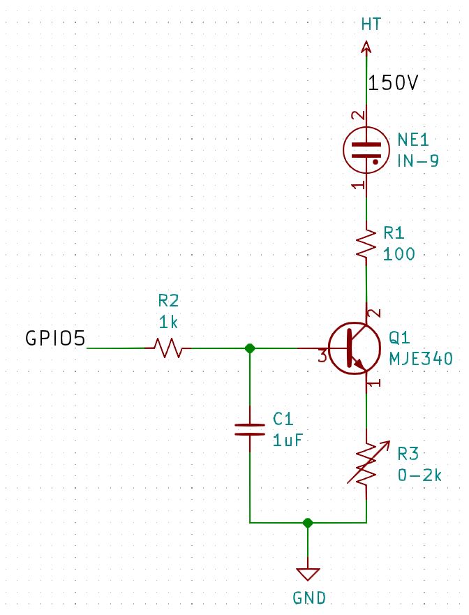
The IN-9 is a very simple tube. Just a single long cathode. As you increase the current (up to about 10mA) more of the cathode lights up, so it is essentially a bargraph. To control the current we attach the collector of a MJE340 transistor to the cathode, the emitter to ground via a variable resistor and then control the voltage on the base. Then we connect the anode to 150V. We could go higher, and adjust the resistor on the cathode to a higher value to keep the tube operating over its full range. I used one of my own adjustable nixie power supplies for this, but there are several supplies available commercially, such as the Taylor Edge power supply and the Omnixie power supply.
I used a Wemos D1 mini pro to control the base, because I happen to have several I’m not using. Because it doesn’t have a DAC we have to fabricate one with a resistor and capacitor and then feed it a PWM signal. So we end up with this:
So now we need to get some sound in to it. I wanted this to be free-standing, so I wanted a microphone of some sort. Eventually I settled on this module from Adafruit. It has auto-gain control and produces a peak-to-peak output that matches well with the 3.3V inputs of the Wemos, and of course Adafruit have code samples for it. In particular a simple sound-level sketch for arduino.
Everything worked great, except for one thing: The glow kept detaching from the bottom of the tube. The IN-9 is well known for this. Most people recommend you use IN-13 instead, but that’s not what I had. Eventually I discovered this article about an IN-9 thermometer. The authors reasoned that the tube was originally meant to be driven via AC, so if they turned the tube off periodically it should work, and it did. They used a hardware solution, but I used a software solution, I just interleaved a PWM signal with the analog output, so it turned off completely every so often. This is the whole code:
#include "Arduino.h"

/*
 * Sometimes you just want to do things according
 * to a duty cycle other than toggle some GPIO.
 *
 * Sometimes you want to run multiple
 * duty cycles on one output pin? You could use several
 * of these to figure out when to turn it off and when
 * to turn it on.
 */
struct SoftPWM {
	byte quantum = 1;
	byte onPercent = 100;
	int count = 0;

	SoftPWM(byte onPercent) {
		reset(onPercent);
	}

	SoftPWM(byte onPercent, byte quantum) {
		this->quantum = quantum;
		reset(onPercent);
	}

	bool off() {
		count = (count + quantum) % 100;
		return count >= onPercent;
	}

	void reset(byte onPercent) {
		this->onPercent = onPercent;
		count = 0;
	}
};

// ESP8266 pins
const byte CTRLpin = 5;
const byte INpin = A0;

void setup()
{
	pinMode(CTRLpin, OUTPUT);
	// Freq and Range are ESP8266-specific calls.
	analogWriteFreq(4000);
	analogWriteRange(100);
	analogWrite(CTRLpin, 75);
}

SoftPWM oscillator(90);	// A 90% duty cycle for turning the tube off. Pick something that works.

const int sampleWindow = 50; // Sample window width in mS (50 mS = 20Hz)
unsigned int sample;
unsigned long startMillis = 0;
unsigned int peakToPeak = 0;   // peak-to-peak level
unsigned int signalMax = 0;
unsigned int signalMin = 1024;

void loop()
{
	// collect data for 50 mS - code based on https://learn.adafruit.com/adafruit-microphone-amplifier-breakout/measuring-sound-levels
	// but this code externalizes the loop, because we don't want
	// to hold the whole ESP8266 up
	if (millis() - startMillis < sampleWindow) {
		// Set the min and max levels over a 50ms period.
		sample = analogRead(INpin);
		if (sample < 1024)  // toss out spurious readings
		{
			if (sample > signalMax) {
				signalMax = sample;  // save just the max levels
			} else if (sample < signalMin) {
				signalMin = sample;  // save just the min levels
			}
		}
	} else {
		// Done sampling, calculate the peak-to-peak level in the last 50ms.
		startMillis = millis();
		peakToPeak = signalMax - signalMin;  // max - min = peak-peak amplitude
		signalMax = 0;
		signalMin = 1024;
	}

	if (oscillator.off()) {
		// Keep the glow stuck to the bottom by turning the tube off occasionally
		analogWrite(CTRLpin, 0);
	} else {
		// Output the sound level
		analogWrite(CTRLpin, map(peakToPeak, 0, 1024, 0, 100));
	}
}
Here’s a video of it in action. The quality (of the video) isn’t great:
I’ve got a few more of these tubes, so now I have to decide if I want to make stereo VU meter or a spectrum analyzer. I think I would prefer to make a multi-purpose bar-graph display like this one from Nuvitron.
Nice write up on the in-9, I appreciate the chance to see your experience with it before I take a crack at it myself. The ac drive/ turn it off periodically business would have thrown me for a loop for sure. The music was a nice touch too, exactly the thing to feed into a tube VU meter