Normally this wouldn’t be much use, but I own a Tesla Model 3, and you might be aware that there is no instrument cluster in front of the driver for these cars – everything is on the large iPad-like display in the center of the console. I don’t really miss having the instrument cluster directly in front of me, its something you just get used to, but it is a good excuse to develop something that I would actually use.
The first decision to make is how to obtain the speed of the vehicle. Here there are two choices. One is to use OBD-II port, the other is to use a GPS module. I opted to use a GPS module because it is less invasive – I wouldn’t have to wire it in to the car’s electronics (also, a Tesla has multiple ports that are like OBD-II but not quite!). The drawbacks of using GPS are that it can take a while to get a fix on the satellites, and if you are in a tunnel, you’ll lose the signal. I ended up using a CAM-M8Q module because I thought I would use the I2C interface, but in the end I just used the serial interface. UBLOX also make modules that include inertial data that should make loss of signal less of an issue.
It seems that all GPS modules use a standard serial protocol called NMEA that can be used to get data from the device. Most also have extensions to that protocol for things like configuration. Ground speed is a standard part of that interface, so there is nothing fundamentally difficult in getting the speed from a GPS module. I prototyped the device using an Adafruit Metro Mini, which is basically just a very small Arduino. These devices aren’t ideal because they don’t include dedicated serial hardware, I ended up using a software serial package called NeoSWSerial. There are also several libraries that can be used that implement the NMEA protocol in a reliable fashion, but I to hand-code the NMEA protocol myself to fit everything inside the limited memory I had. Basically I should have used a better chip, but hey I like a challenge.
Apart from the getting the data to display, everything else is essentially the same as driving a nixie clock. You need a boost converter to produce the 170V to drive the nixies, you need a high voltage serial-to-parallel converter to select the digits to display and you need some way of programming the CPU. Most of these things can be done with modules, i.e. I could have used a 170V boost converter module and the Metro Mini module and then one of several possible high voltage serial-to parallel schemes, but I just built it all myself because I already had circuit designs that I use in all my other nixie tube devices. I used a HV5523 high voltage shift register made by Microchip. This is an SMD part, but Microchip make several variations of this device, some of which can be socket-mounted. They are all driven in a similar, though not identical way. My code (link at end of article) uses the Arduino SPI library to handle the low level comms.
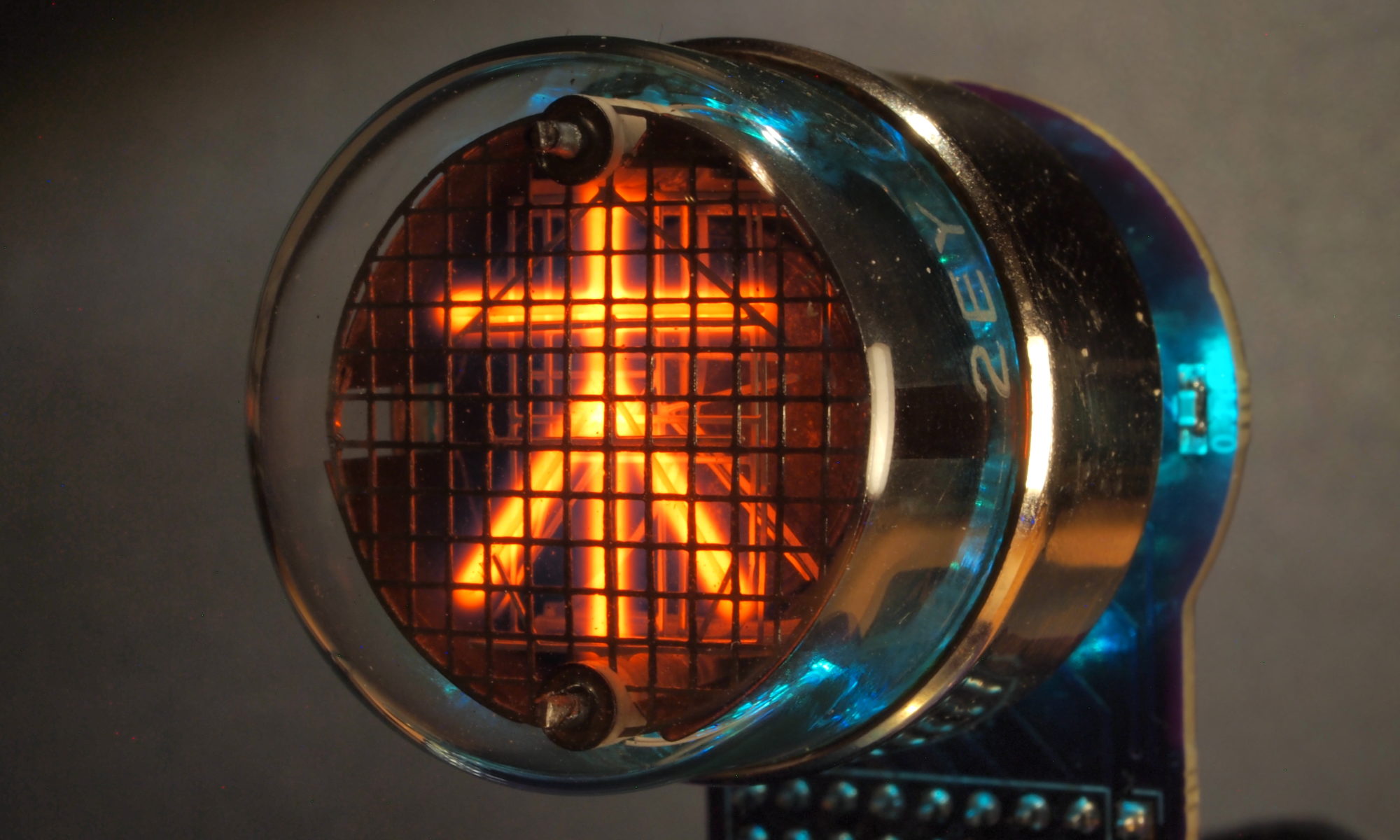
The final thing to select was the nixie tubes, and I happened to have some Tesla ZM1020 tubes, which are the perfect size and I thought it would be fun to use tubes manufactured by a company called Tesla for a device used in a car also manufactured by a (different) company called Tesla.
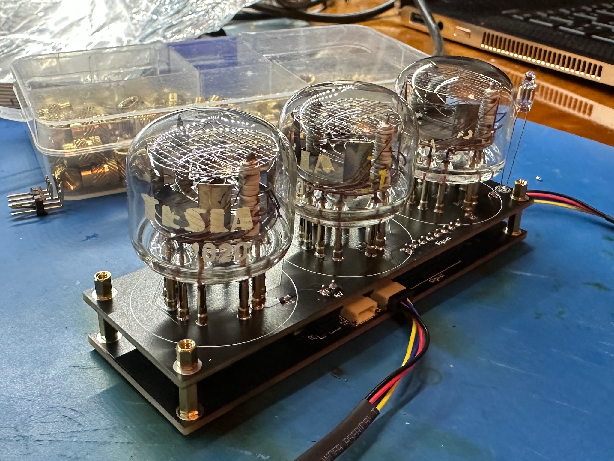
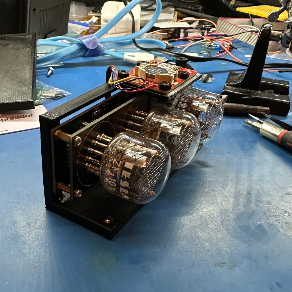
Above you can see the guts of the speedometer. In addition to the nixie tubes, there is a small neon indicator that I use to indicate when the device is still trying to get a fix on the satellites.
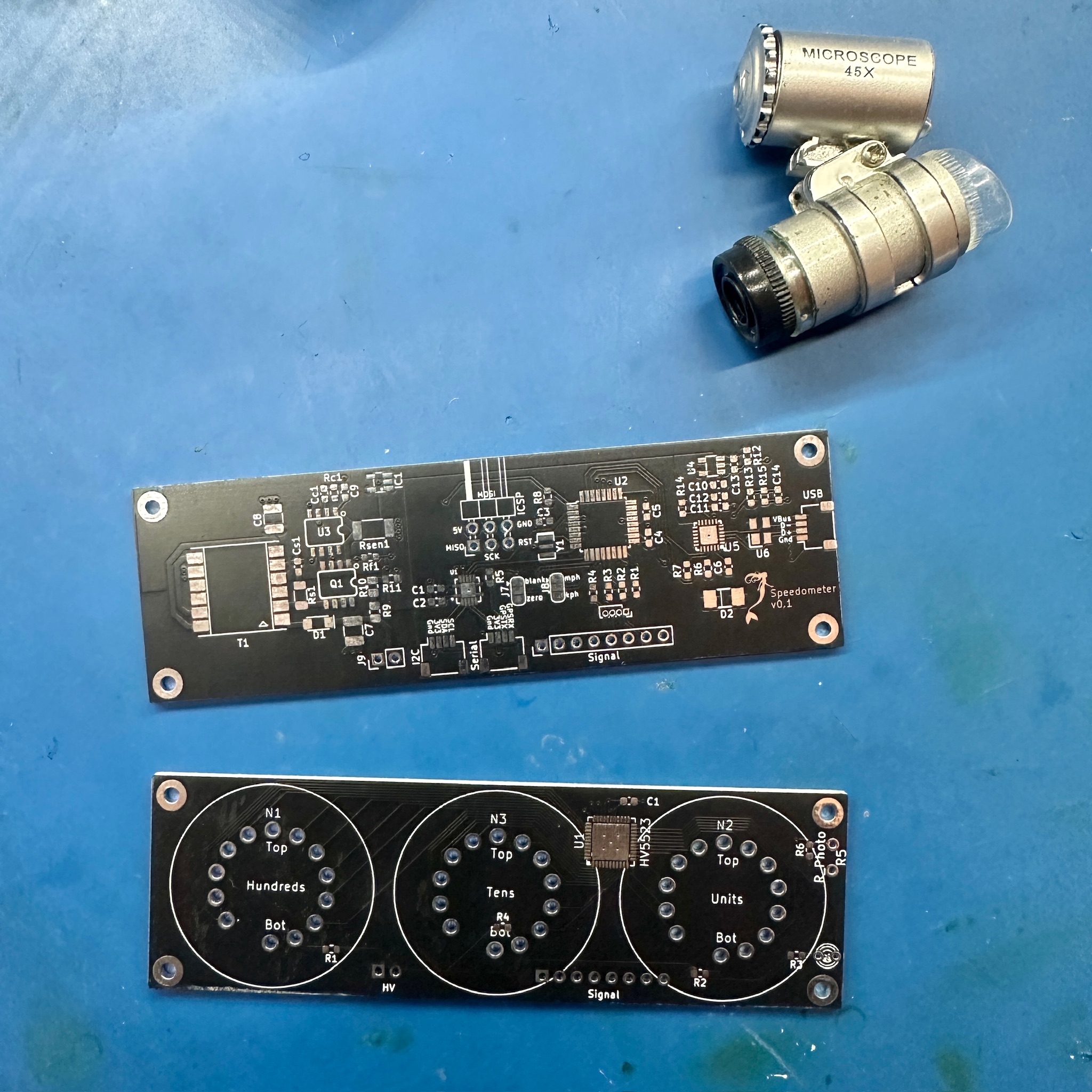
The basic design uses a stack of two boards, one for the main electronics and one for the display. I designed these in KiCAD and had them made by JLCPCB. There are basically three sections to the main PCB, on the left is the 170V boost converter, in the middle is the CPU and I/O, on the right is the USB interface.
Below you can see everything assembled ready to go in the enclosure – note the GPS module at the top.
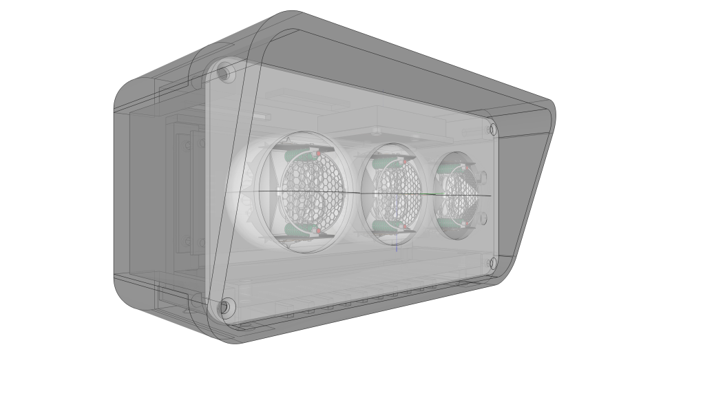
I designed an enclosure for the device in FreeCAD and printed it on my 3D printer. The render below shows the final version.
I printed the initial version in PLA, but this is not a good long term choice – temperatures inside a car can easily get high enough for PLA to soften and deform – so after using this design for a while I had a version of it printed in Nylon by JLCPCB. The photo below shows the PLA version.
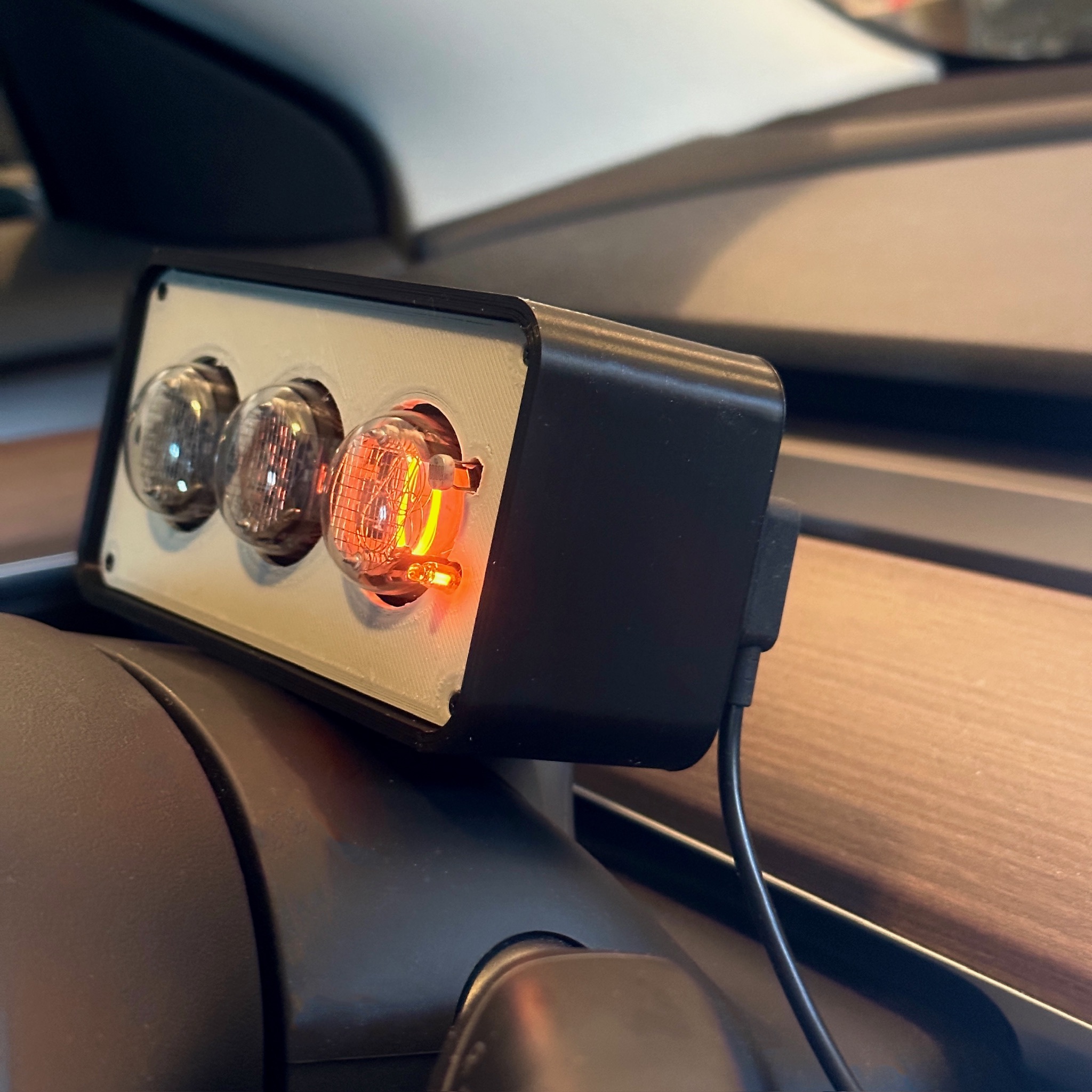
In the above photo you can also see the power lead – the unit just plugs in to a USB port, all the other voltages are derived from 5V. I found a magnetic USB cord and socket on Ali Express. I felt this would protect the device if I snagged the lead.
You might also notice there is an LDR (Light Dependent Resistor). I use this to detect the ambient light level and dim the display accordingly. This can be done by rapidly turning the nixie tubes on and off – a standard way of adjusting the brightness for nixie tubes – note this does not turn the 170V on and off, it just deselects all the digits.
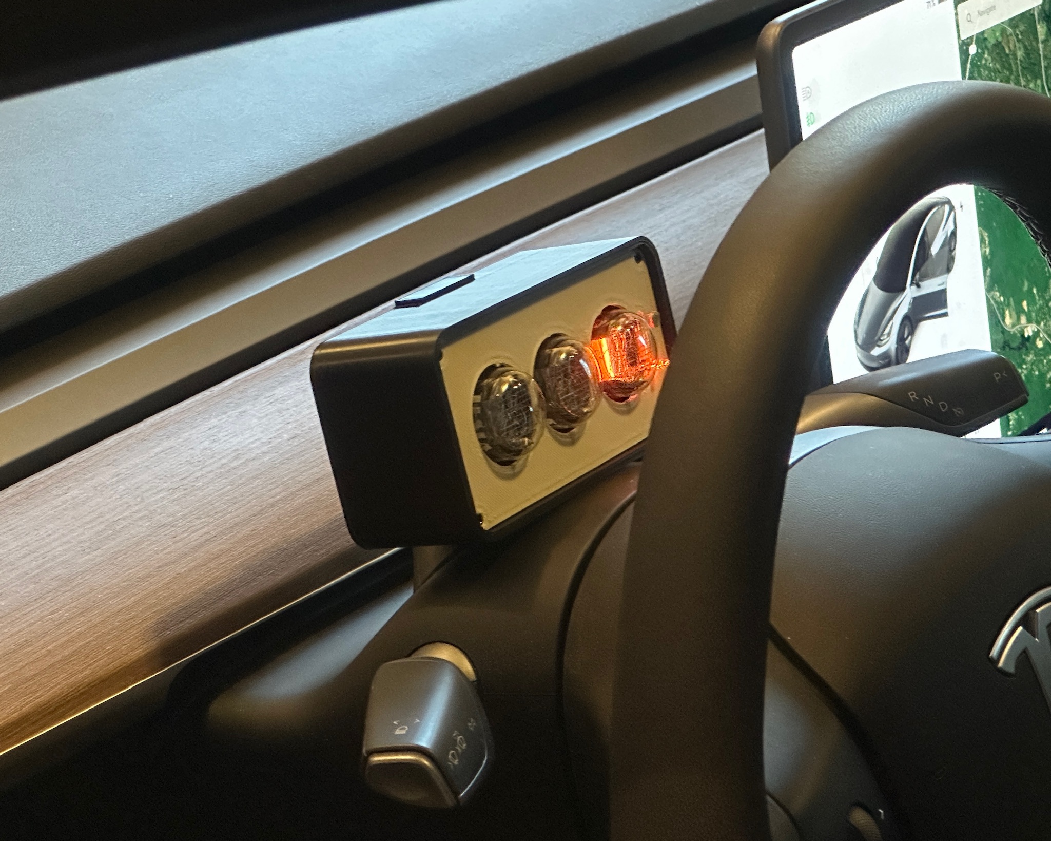
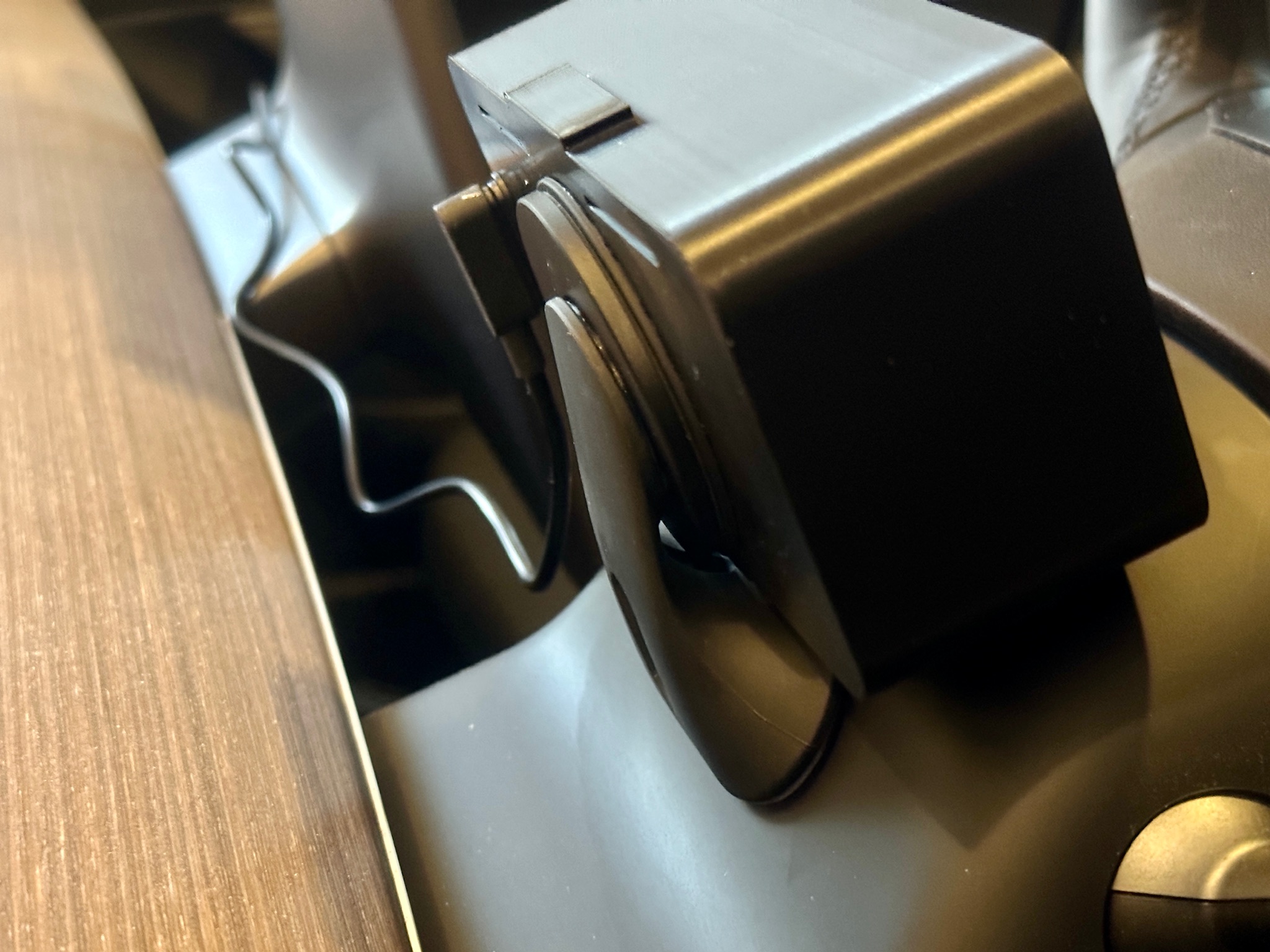
There was also the question of how to mount this to the car. I spent a long time on Ali Express looking at various options and finally went with this magnetic mount, which you can see in the photo below. This has proven to work very well.
Here is a video of it in use:
Code is available on GitHub.