Divergence Meter Setbacks

Firstly, I only ordered one push-button instead of two. Annoying, but not a big deal.

Secondly, the perfboard had logos printed all over it. No chemical would get them off. Sanding didn’t get them off. When I used a dremel, I discovered the pigment went deep into the substrate. I figured that maybe this was just the particular supplier that DigiKey was using, so I ordered some straight from the public BOM on Mouser. It is exactly the same. So I am down $34 on perfboard I can’t use.

Perfboard
Perfboard + Logos

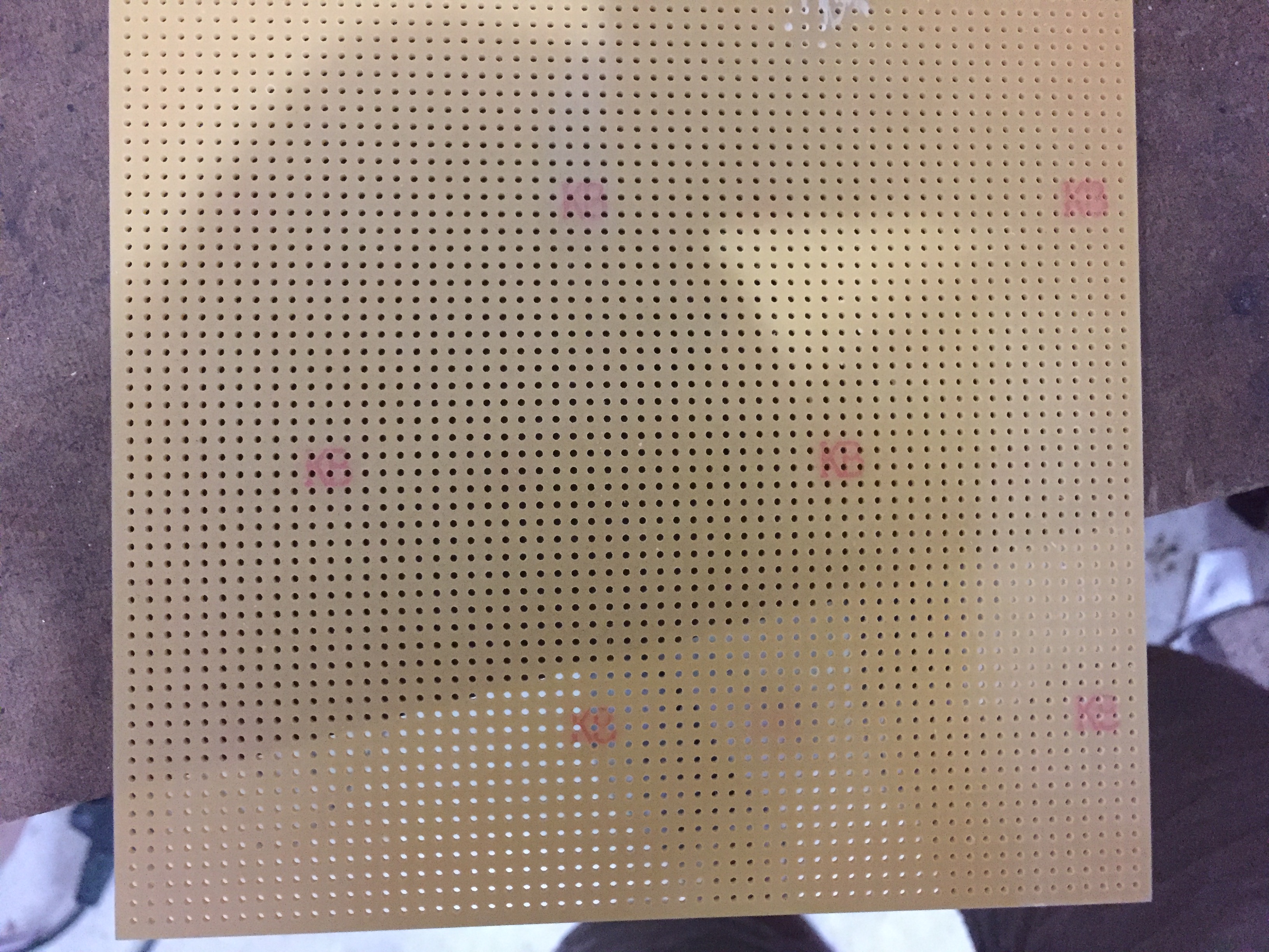
I have ordered yet another perfboard for $23 from DigiKey from a different manufacturer. Hopefully this one won’t be covered in logos. So $57 on perfboard alone. So far!

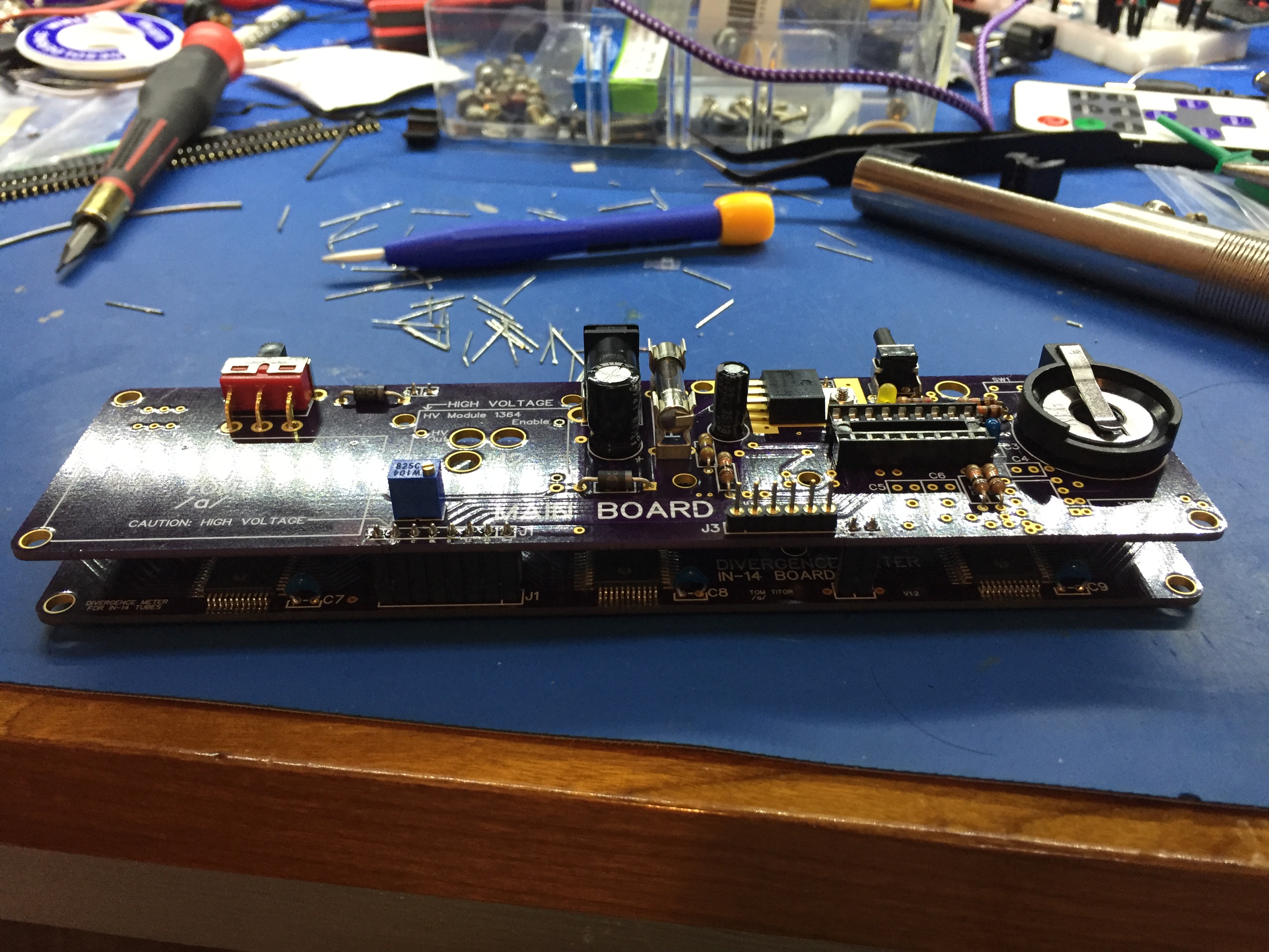
Thirdly, I missed that the boards on OSH Park need an additional diode near the battery switch. Fortunately I had a suitable Schottky diode lying around.

Fourthly, when I was adjusting the HV it mysteriously stopped working, and the PIC started to get hot. I guess I shorted the HV to the PIC, though I don’t recall doing so. So I am down the HV and the PIC. The HV part is $14. The shipping is $10. So I am now down an extra $60 with little to show for it. Plus I had to unsolder the HV. Fun times!

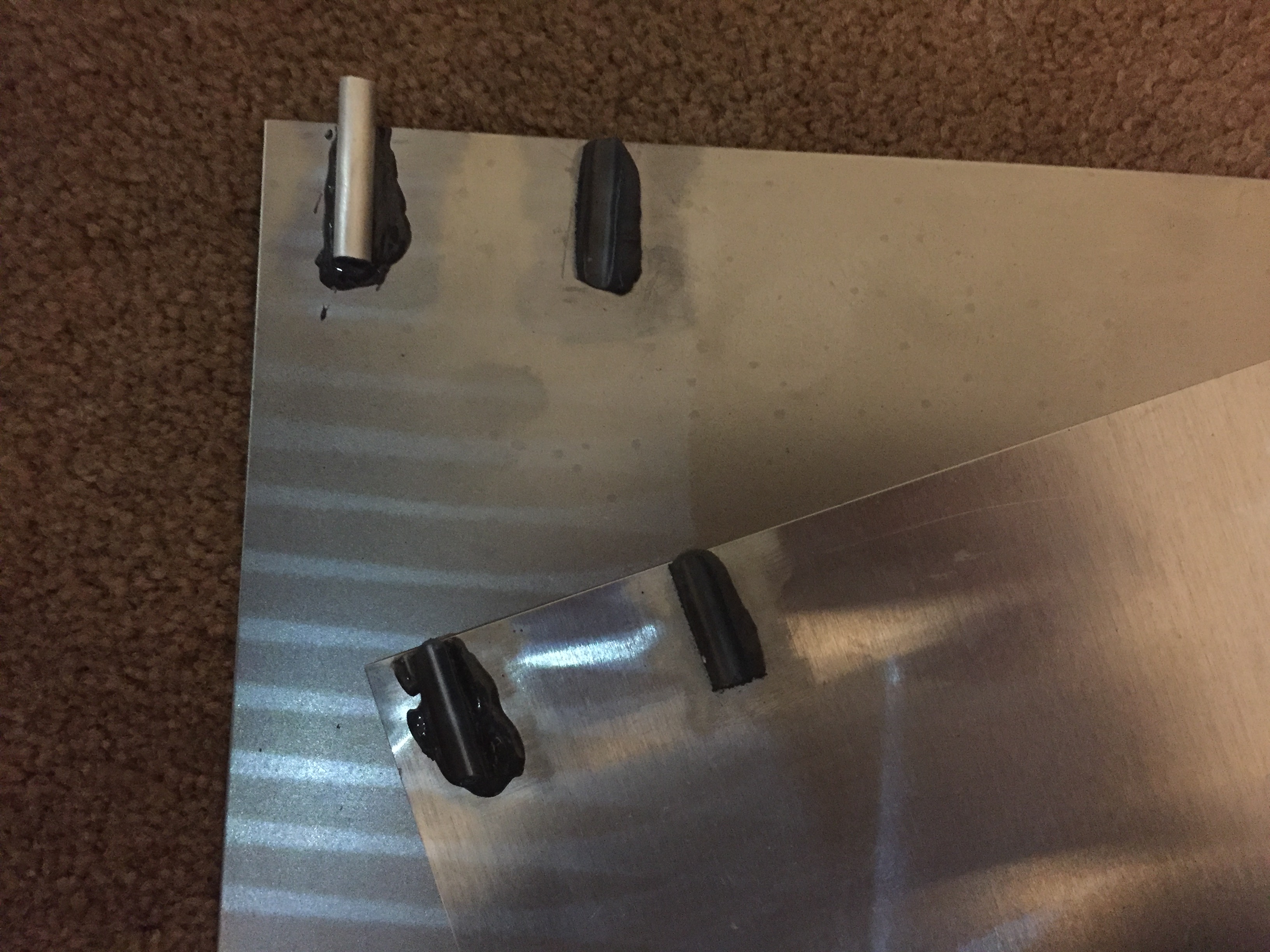
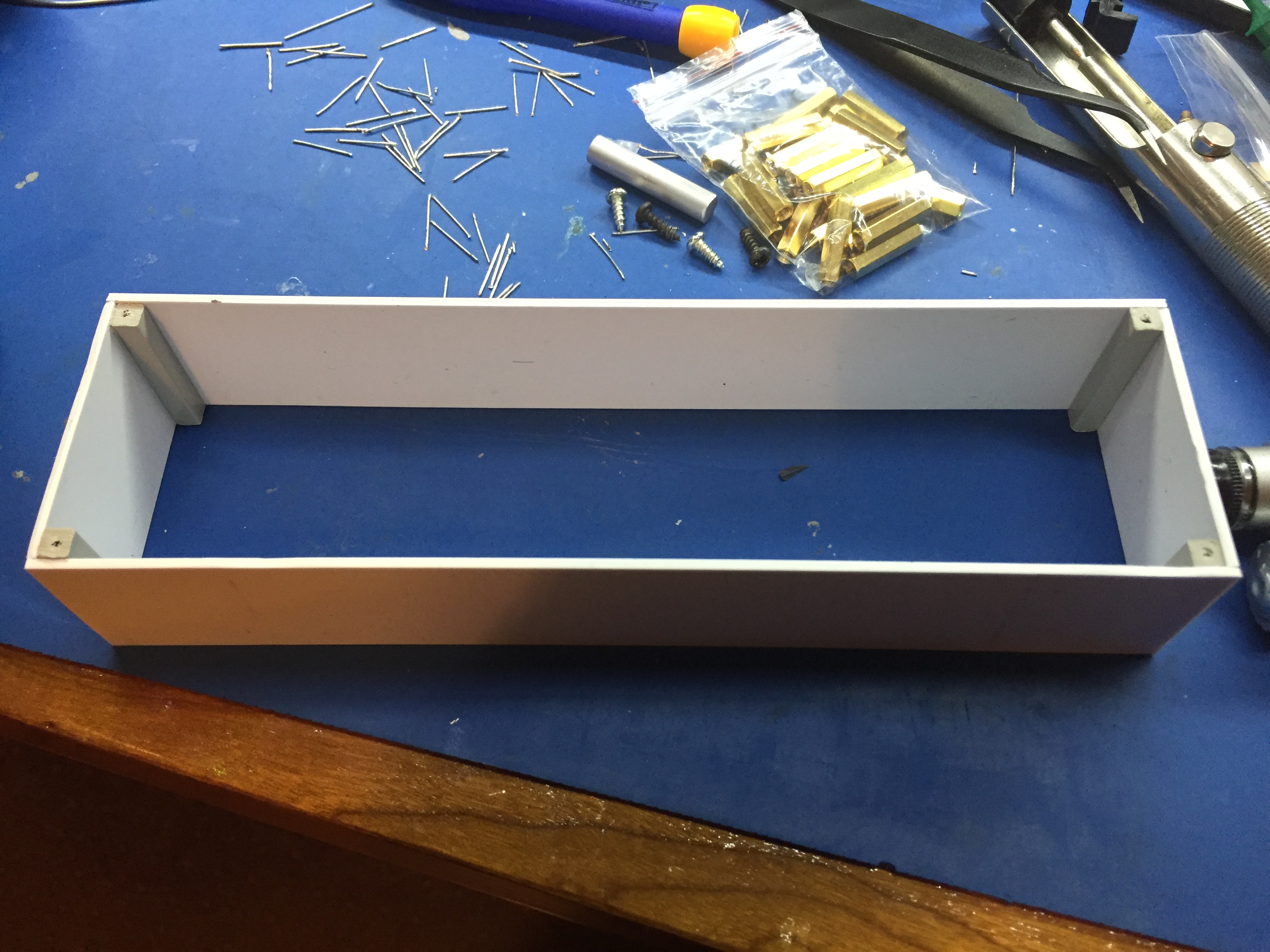
Since there is little else I can do at this point, I built a prototype case with the styrene sheet. This is so I can test the positioning of the openings on the case before I get some metal ones fabbed.

Anyway, here are the boards, with a gaping hole where the power supply should be 🙁

Divergence Meter

Divergence Meter Kickoff

Its time to actually start building this divergence meter:

Divergence Meter Kickoff

I ordered the parts from Digikey, which have arrived. I chose to program the PIC16F628A myself, by which I mean upload the hex file from Tom Titor. Partly this is because I figure I might modify the program at some point. So I bought a cheap pickit 3 copy off ebay.

I’ve also been re-familiarizing myself with SolidEdge 2D as I would like to get the case pieces fabricated, so I will need an accurate CAD model, and I have used SolidEdge in previous projects.

In addition I have been mulling over how to actually build the case. Ideally I would like to make my own posts with a square cross-section and tap them for screws – I really don’t like the idea of gluing things together – however that is way beyond me at the moment. I also toyed with the idea of using styrene sheets  that are used in modelling. So in the end I bought samples of various materials and practiced gluing things together:

Practice pieces for the case

The top sheet is aluminum. The bottom sheet is steel. The left hand blob of glue is JB Kwik, the right hand blob is JB Putty. I glued some aluminum rod to the sheets with an overhang so I could try and pull them off. I roughed up everything with a dremel tool before hand and cleaned it all up with Isopropyl alcohol. In the end I was surprised how strong the bond made by the JB Kwik was, so I am reasonably confident that I can glue standoffs to cut sheets to make the case.

I also glued square rod to the styrene sheets. The bond here was actually pretty good, but they peeled off if I flexed the sheet. When I examined the styrene, it had been softened by the cement. I will probably use the styrene sheets to make some prototypes from my drawings to check that I got all the measurements right.

Now I need to start some soldering.