Nixie Clock With Vacuum-tube Power Supply – Part 5

This is the fifth post about a nixie clock project that is powered by a vacuum tube power supply, rather than the more common 12V or 5V wall wart.

After part 3, I took a brief detour to talk about the controller hardware, and I had left off talking about the lack of a 5V supply. I had originally hoped to power everything from the mains transformer, but my choice of vacuum tubes made that impossible, because they pulled the 5V and 6V3 supplies up to a high potential, and my circuitry needs to share a 0V rail with the HV supply.

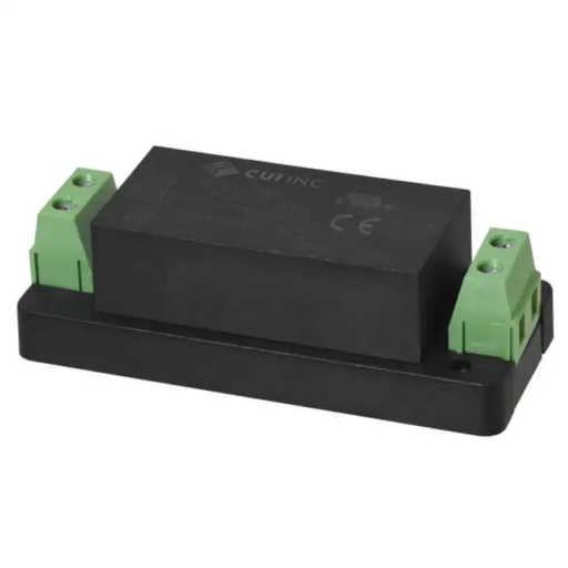
The other aspect of all of this, that I hadn’t managed to resolve, was that I wanted to be able to turn off the HV from the control circuitry. I had mulled over just severing the input the rectifiers (because I wanted to keep the 6V3 winding alive for the 5V DC rail), but now that I couldn’t use that anyway, the problem was solved. I would just use a separate 5V supply and use a SSR (Solid State Relay) to control the mains input to the transformer. I went with a fully enclosed chassis mount 5V supply from CUI.

CUI PSK-S6C-5-T

One final thing I added was a varistor across the input to protect against voltage spikes. One thing I wish I had added, but didn’t, was an inrush current suppressor.

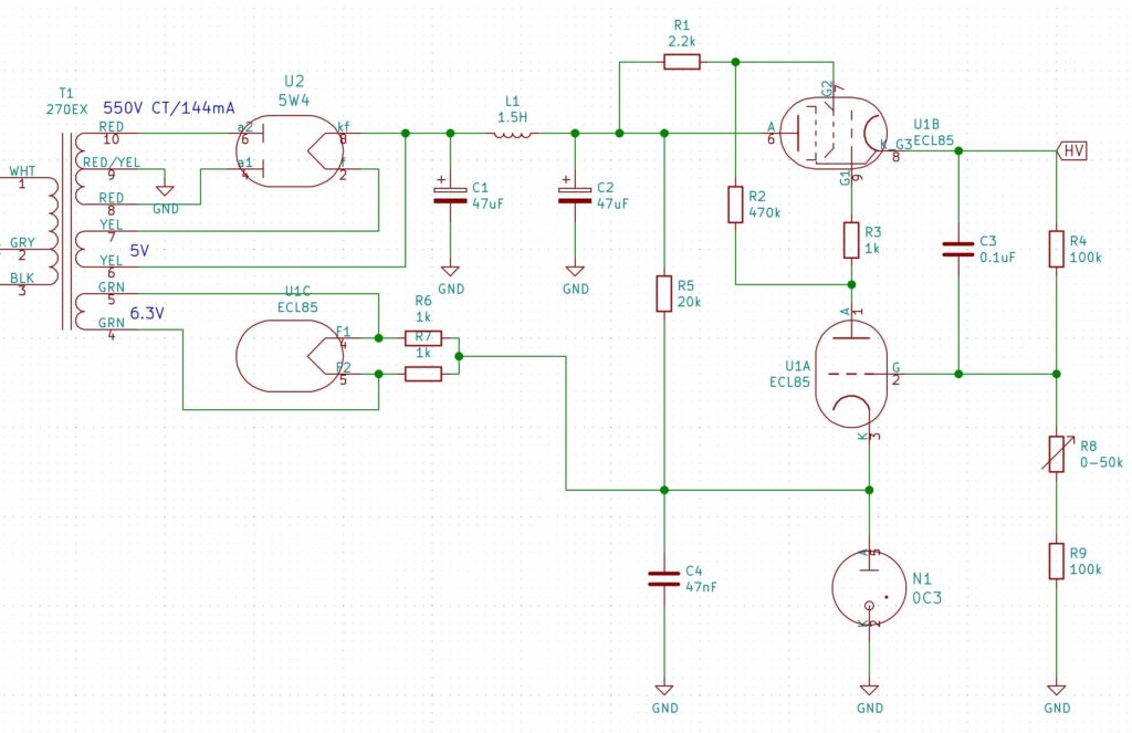
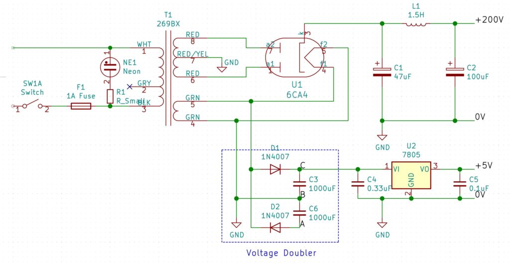
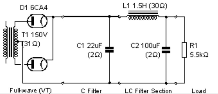
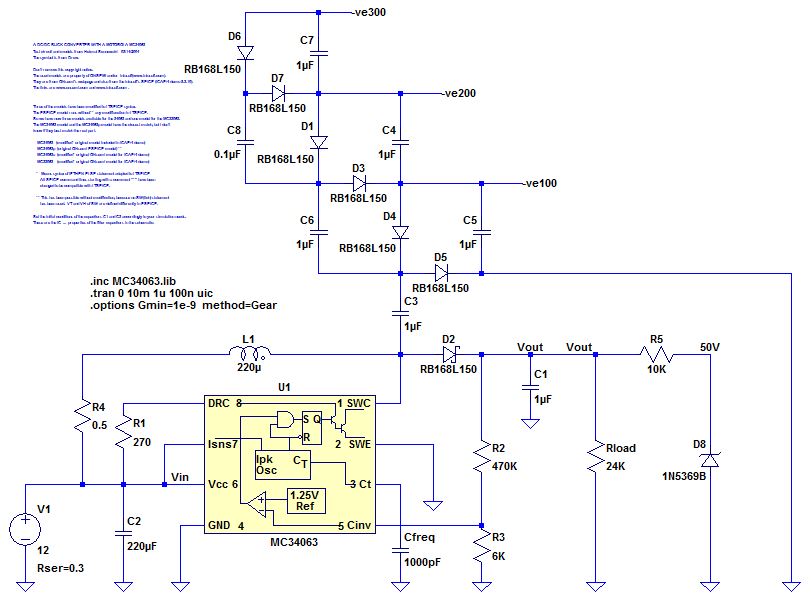
So anyway, this is the final final circuit:

Final Final Power Supply

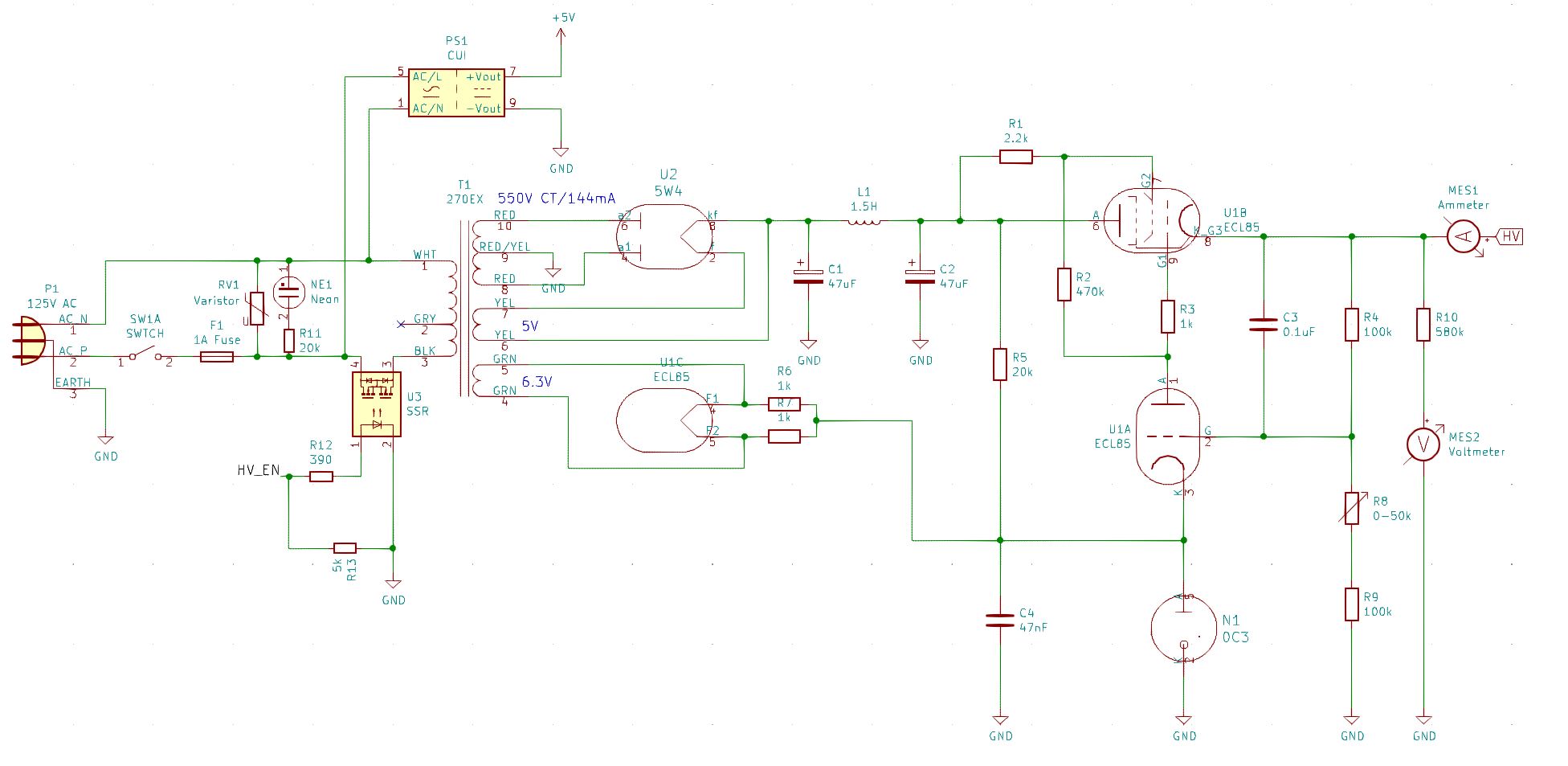
You’ll notice that this circuit includes a voltmeter and an ammeter. I had originally intended to add a voltage/current display using CD13 nixie tubes, which are very small, but I decided this was a step too far. In the end I went for a couple of analog meters because I could put them in the high side, unlike digital meters. I felt that they also matched the aesthetics better than digital meters would. They aren’t just for show. I wanted a simple way of monitoring the voltage and current over time so it would be more obvious if things were starting to drift.

Voltage and Current Meters

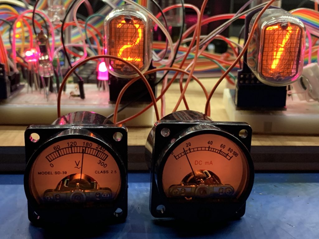
You might notice that the voltmeter is for AC (the ~ symbol under the V). I took one of these apart to see what was inside, and it is just a diode to rectify the voltage, so it would be fine with DC too, but I would have to add a resistor in series to re-calibrate it for DC.

These were the smallest, old-style meters I could find, and they included the internal illumination. I drove the bulbs off the 6V3 circuit, so they are a little dim, but that is OK by me.

Nixie Clock With Vacuum-tube Power Supply – Part 1

About 7 months ago, I watched a video by glasslinger about adding a nixie tube display to a vintage radio. This was something I had wanted to do for a while, but I didn’t know how to read the tuned frequency from the radio. There were many interesting parts to the video (I recommend you watch it), but one of the things I learned was that vacuum tube radios that had tranformers, actually generated voltages with those transformers that were high enough to drive Nixies.

I spent a little while trying to find a radio with an input transformer like that, and in the meantime, I started researching vacuum tube power-supply design. That was when I finally realized that these things were still being made for guitar (and HiFi, but especially guitar) amplifiers. So you could actually buy new transformers and new vacuum tubes and new chokes that you could use in a new power supply. That is when I got really serious about this.

At this point, two sites influenced my initial design. The first was ‘Fun With Tubes’, which had several simple designs. The second was ‘DIY Audio Projects’. which went in to much greater depth about tube selection and circuit calculations. In particular, the latter had a nice chart showing the voltage drop that different vacuum rectifier tubes had. Some of them were quite startling – for example the 5Y3, used by the first site, had a voltage drop of almost 45 volts for a plate current of 100mA, compared with only 15V for the 6CA4. What’s more, the 6CA4 is still in production.

The DIY Audio projects site showed a long series of manual calculations to determine properties of that simple un-regulated power supply. I entered these in a spreadsheet to make life easier, however, I later found a little application called psud2 (power supply designer 2) that did the same thing using a simulator and a few values from the data sheets. The important thing being that the maximum 6CA4 plate current (which is on a cold start) does not exceed the maximum allowed plate current on the data sheet.

Taking a hint from the DIY Audio Projects page, I decided to go with a one-stage choke filter to smooth the output of the rectifier tube. Confusingly (for me) everyone refers to this as the ‘input filter’. I guess because it is the input to whatever comes after this stage – usually an amplifier. So this is what I ended up with (from dsud2):

Unregulated vacuum tube power supply

Obviously(?) this is just the output stage. On the input side is 125V 60Hz, a 1A slow blow fuse in the hot line and a neon indicator across hot and neutral, so I could tell when it was on.

Something I omitted was a resistor to drain the capacitors when power was removed. Those capacitors can hold a charge for a long time. I soon added one. Experience is wonderful thing.

Here is a chart from psud2 showing the expected output:

Power supply simulation

The next stage was to select some actual components and bread-board it. I ended up going with a 269BX transformer from Hammond, a 156R choke (also from Hammond) and a new 6CA4 from JJ Electronics. All the rest are just suitably spec’d parts from DigiKey and a bunch of terminal strips, screws, fuses, switches, fuse holders etc. from my local electronics store.

I would show you a picture of the breadboard, but I will save that for part 2, when I discuss how to deal with the potential for voltage sag.

ITS1A Power Supply Part II

As I delved more into making a power supply for the ITS1A thyratron, the design became more complex. For example, to produce 100V from the inductor I would need an external FET. To switch the FET properly, I would need another transistor. If I was going to do that, I would use a completely different chip in the first place. So I re-considered what I was trying to achieve, which was simply to light up one of my tubes, just to prove that I could. So I used an existing 50V power supply I had built using the MC34063, and just built two Cockcroft -Walton ladders – a regular voltage doubler for the +100V, and a ridiculous ladder with 12 diodes for the -300V. Actually the data sheet (which I translated with the help of an online OCR and google translate) says that should be -250V. So that is what I used. Here is a picture:

A 6x voltage multiplier

I verified all the voltages, then the next step was to figure out what pins did what. Careful examination of the tube showed that two pins were cut short – this correlated with two pins described as ‘free’ on the data sheet and that allowed me to figure out what went where:

Physical pin descriptions of the ITS1A

Translated description of what the pins are

So with this I was able to wire the tube up and get it to glow:

Glowing ITS1A

You can clearly see the detail of how the phosphor is activated.

What I haven’t been able to do is to control which segments are on an which are off! It is clearly something to do with grid two, but I haven’t been able to figure it out yet.

ITS1A Power Supply

I have been meaning to get some ITS1A thyratron display tubes for some time, and finally bought some a few weeks ago. These are a seven segment display tube that looks a little like a VFD tube when on – they use the same phosphor – but they are driven entirely differently.

An ITS1A on ebay

Although they can be controlled with logic-level signals (roughly 1V to 5V), they require a bizarre set of voltages to actually activate them. The data sheet specifies around 40V, 100V and -240V. Others have apparently driven them with 50V, 100V and -300V. Yes, that’s right, that is minus 300V.

Now I don’t happen to have a power supply lying around that can produce that range of voltages, but it is surprisingly easy to build one. Or at least design one. I haven’t built it yet. The principle is to first build a simple boost converter, then use  a Cockcroft-Walton voltage multiplier driven from the un-rectified output of the inductor, to get the negative voltage. I simulated one in LTSpice. I set the output voltage to 100V. Built a diode/capacitor ladder for the -300V and used a 50V zener diode voltage clamp to create the 50V. This is what it looks like:

A boost converter that will produce the voltages needed to drive an ITS1A

This is what the simulation looks like:

Voltage plots for the boost converter

The part numbers for the diodes are just examples. I haven’t actually chosen them yet. Both the diodes and the capacitors in the ladder need to be able to handle over 100V. The capacitors should be low ESR types. The inductor needs to be able to handle the expected current, though I haven;t figured out what that is yet. However my aim with this is to just be able to test that the tubes work, and maybe have a little fun with them. An actual clock will come later.