In Part 1 I covered the genesis of this project and my first stab at a vacuum tube power supply.
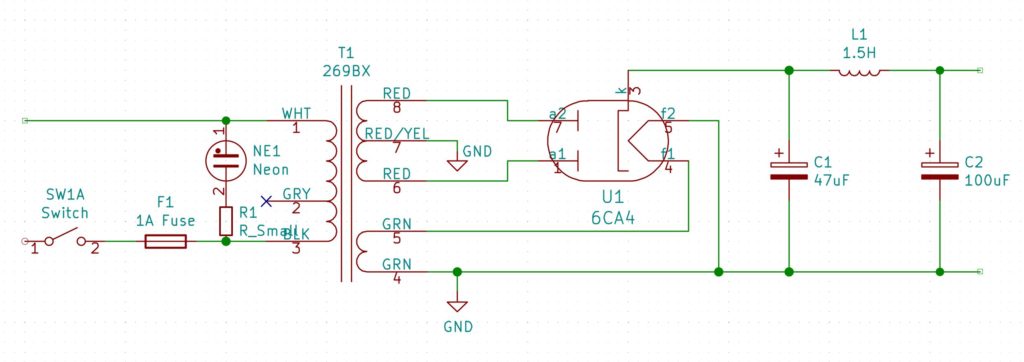
One of the things I wanted to do was provide all of the power for the clock from the transformer. My regular clock circuit only needs 5V, so I figured I could get this from the 6V3 filament winding using a bridge rectifier and a 5V voltage regulator. This is only really possible because the 6CA4 rectifier tube uses an indirectly heated cathode. That is to say, the heater is not connected to the output pins, so it can be at any potential with respect to the output voltage. In particular, it means we can tie one side of the heater to the common ‘ground’ or 0V rail. The HV ‘ground’ is the center tap of the secondary:
Some of you may have figured that that is cutting it a bit too fine. A bridge rectifier using regular diodes could drop around 1.4V to 2V depending on the current draw. The voltage regulator would drop another 2V, so it needs a steady 7V in. So if the smoothing were perfectly efficient, we would go from 8.9V (6.3*1.414) to possibly less than 7V. Simulation with LTSpice shows this is optimistic.
Another alternative would be to use Schottky diodes for the bridge, and simulation show this would probably work. However, I decided to use a simple voltage multiplier on the 6V3 AC which gives me better smoothing for fewer components. So the whole circuit now looks like this:
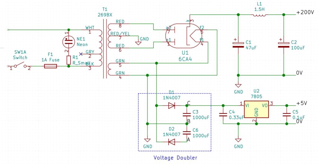
You’ll note that this diagram is slightly different. I have cut the direct connection between pin 4 of T1 and the 0V rail of the HV section. Instead I have explicitly shown each section (the voltage doubler, HV and 5V sections) with a separate connection to ground. This is because, as it is, I am only using one half of the voltage doubler. This is just one diode drop, rather than two (as with the a full-wave bridge), so the voltage is enough for the 7805 regulator. If I wanted to use the full doubled voltage, I could just move the voltage-doubler ground to the point labelled A instead.
This is all very well, but it turns out to have a couple of draw-backs, as will become apparent later.
Current Limiter
The HV power supply is unregulated – which is to say, as you draw more current, the voltage starts to sag. This is because the forward voltage drop of a rectifier tube increases as the current increases. To get around this I decided I would use a small constant-current circuit to drive my Nixie tubes, in place of the usual current-limiting resistor. This basically works by connecting the source of a PMOS transistor to HV via a resistor (Rset) and then biasing the gate a fixed voltage below HV (Vgs) like so:
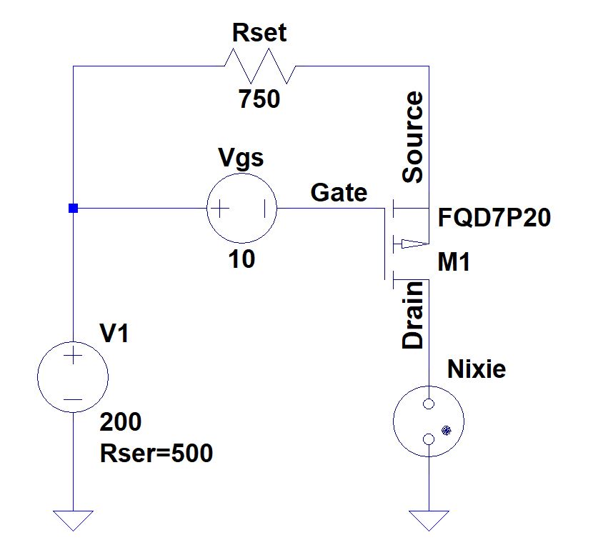
This is the equation for the resistor, given the desired current (Id):
Where Vgs(on) is the voltage drop between the source and the gate, which you can get from the transfer characteristics chart of the data sheet. A rough estimate would the typical gate threshold voltage.
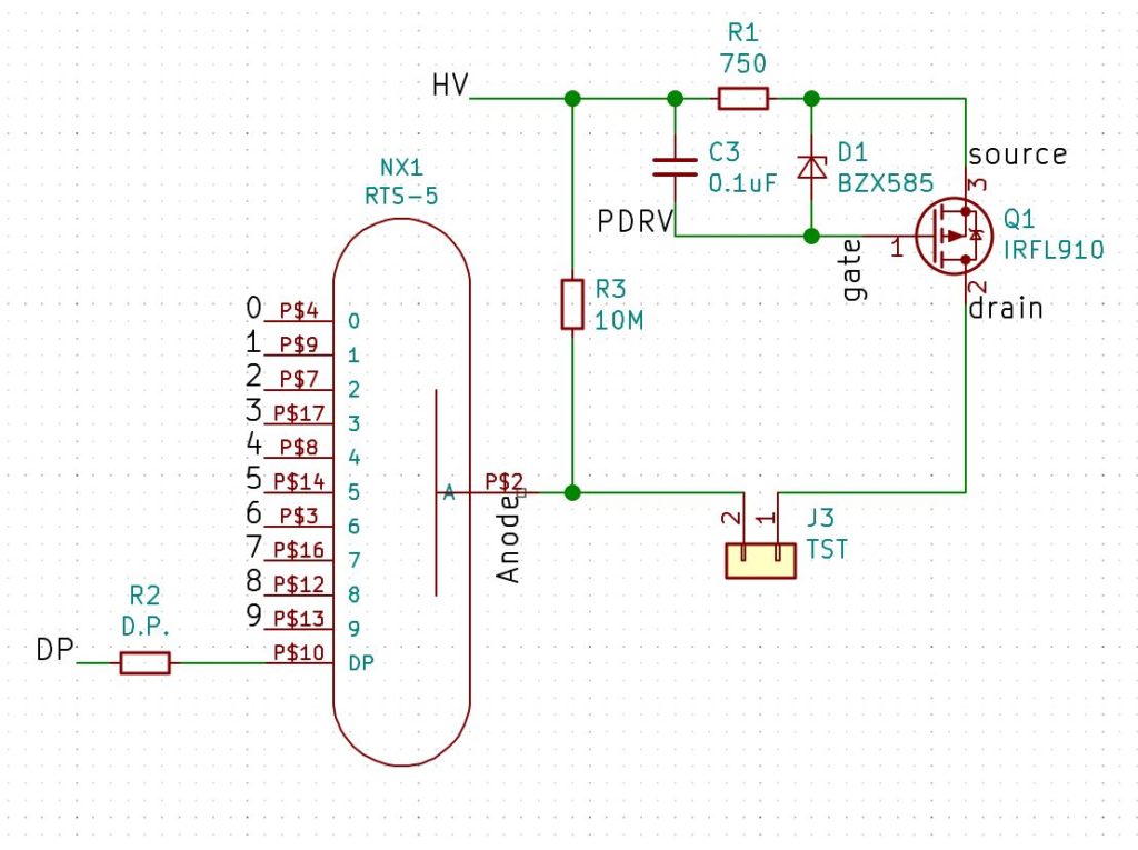
Of course, the trick is to keep Vgs constant, even though HV is varying. To this end, I used a small isolated DC-DC converter to boost 5V to 12V and then attach it to the circuit as shown above. The gate takes virtually no current, so the boost converter can be very small. Using a voltage divider let’s us get to 10V and using a small potentiometer in one leg of the voltage divider allows us to adjust the voltage to get precisely the current we want.
Following some advice I received on the Neonixie google group, the actual circuit is a little more complicated, to provide some protection to the MOSFET. I designed some boards to act as sockets for the nixie tubes that included all this circuitry:
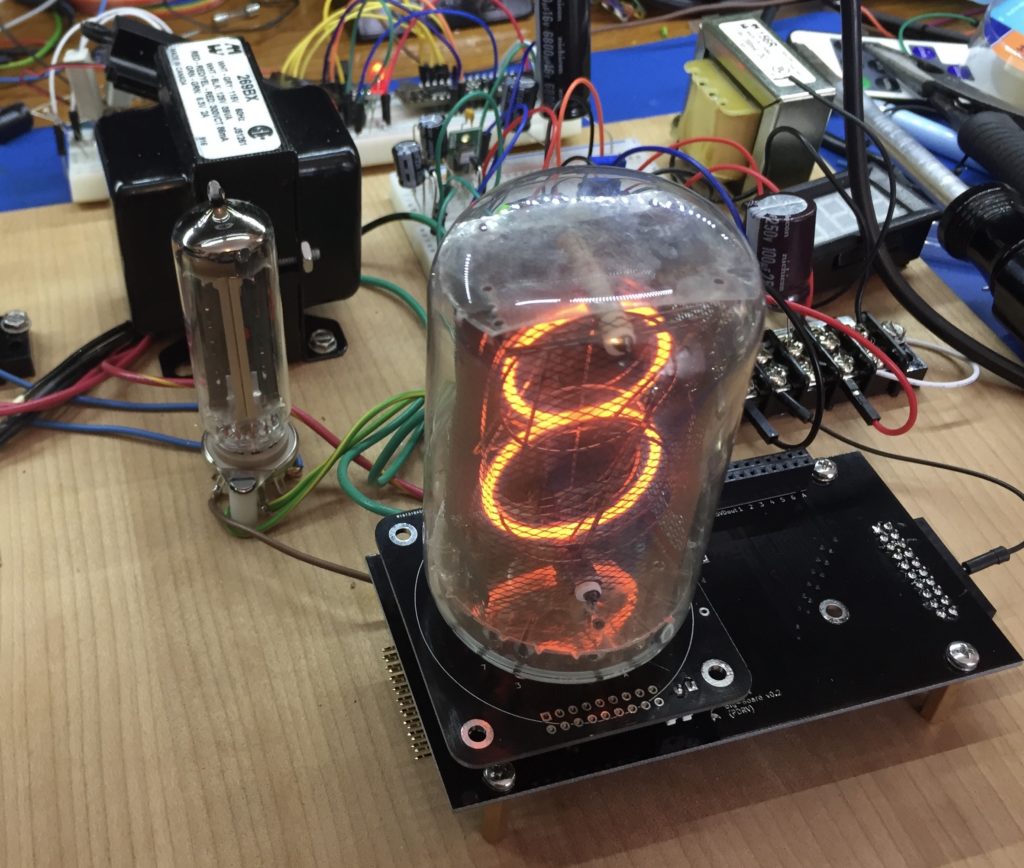
At this point I had decided I would ultimately want to use all of this to build a clock that would feature the large NL7037 tubes I had been collecting. I had been meaning to build a clock with an industrial feel to it to match the look of these tubes, and I felt that this would be the one. Finally here is a shot of a test I made using one of the tubes and adapters: