Nixie Clock With Vacuum-tube Power Supply – Part 3

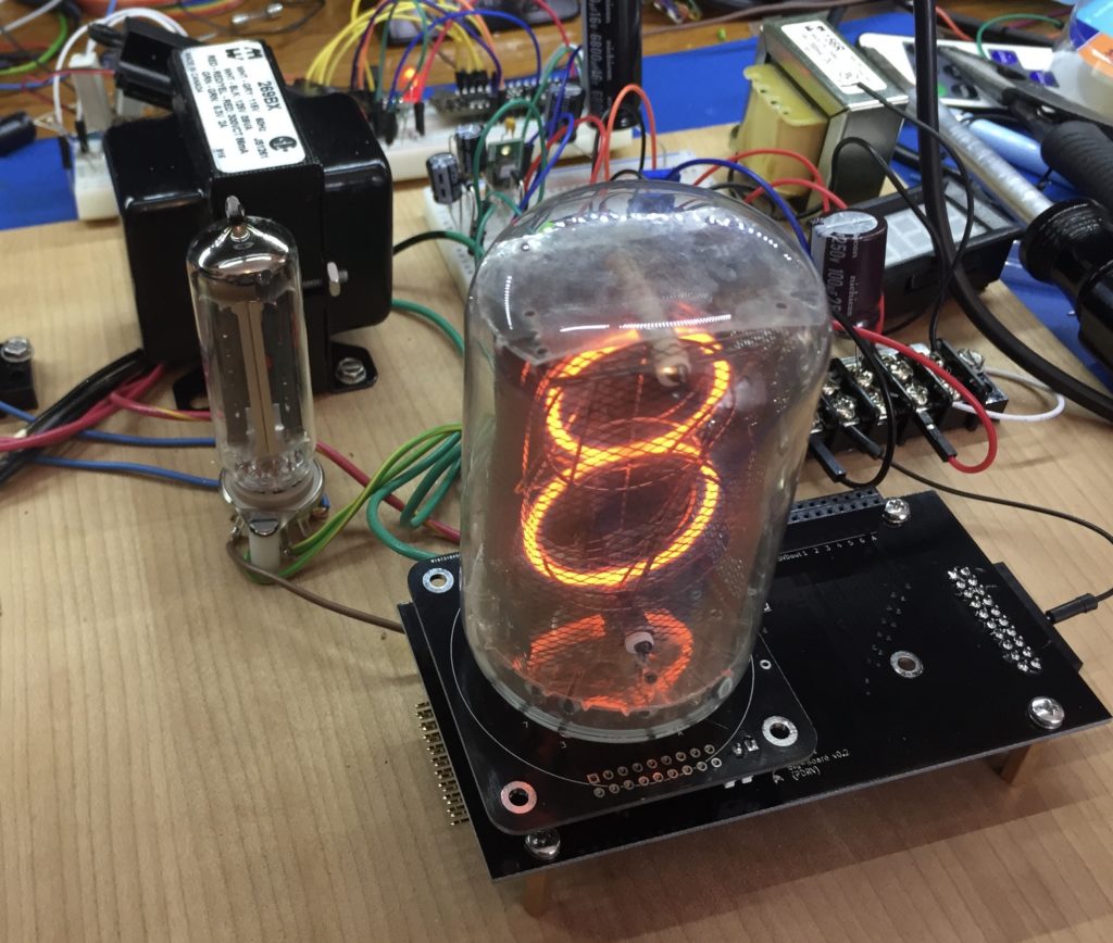
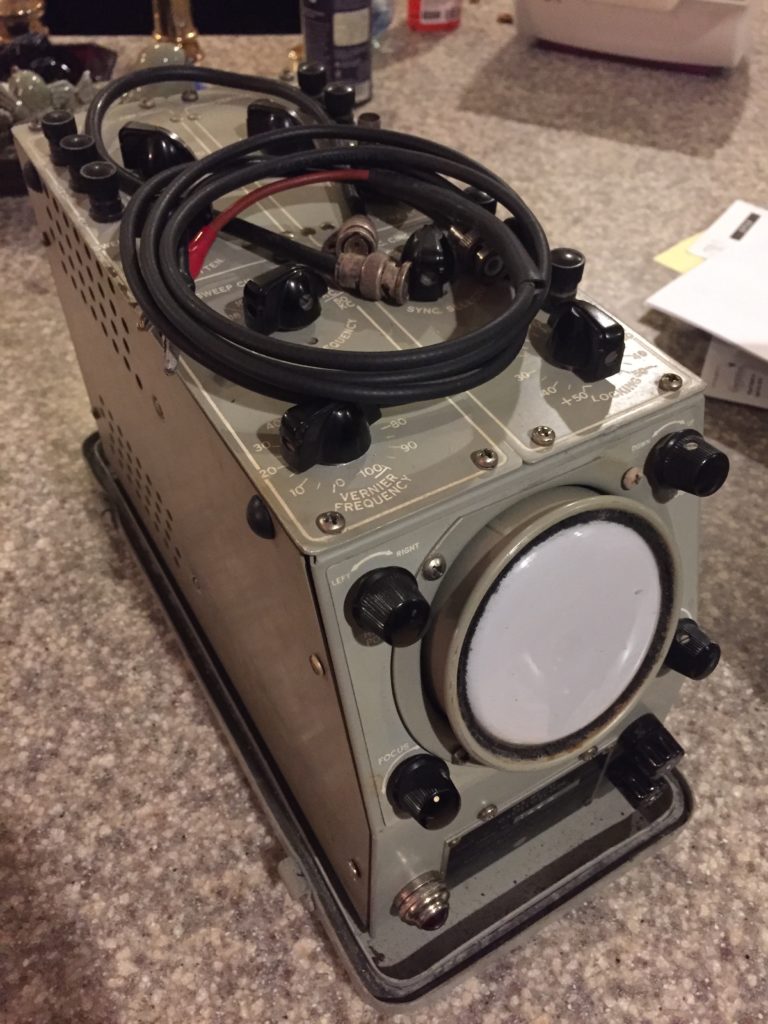
So I had a functioning prototype (see the end of Part 2), but at about this time I bought an old oscilloscope:

Old Oscilloscope

So I started looking around for oscilloscope clock kits and eventually I hit this site (which is an overall fascinating site). That site had a page that introduced me to voltage regulator (VR) tubes. He was using two tubes called 150C2 (aka 0A2) to provide +150V and +300V.  Now the great thing about VR tubes (for me) is that they are also cold-cathode tubes – i.e. they contain some mixture of noble gasses, and they glow. It looked like I could easily produce a regulated power supply using these tubes, but of course there was a catch – or several in fact:

  1. These are like nixies or any other neon tube – they need to be current-limited. The 0A2 will take a maximum current of 30mA. The way that Grahame was using them was to tap off the required voltage after the current-limiting resistor. So that resistor had to be sized to allow the minimum required current for the VR tube (5mA in the case of the 0A2) + the maximum current for the nixie tubes. I was planning on drawing around 50mA, so I would need a resistor that limited the current to 55mA. However when all the nixie tubes are off, that would mean the 55mA would be flowing through the VR tube, which exceeds its maximum by 25mA. I suppose I could have used several in parallel, perhaps even one VR tube for each nixie tube! However there is the second issue:
  2. The regulated voltage that they establish is, at the most, 150V (different VR models have different maintenance voltages). Again, I could use two in series, but now we are getting a little ridiculous.

It was time to do some more research. The solution is to use the VR tube to produce a reference voltage and then construct a feedback loop that measures the difference between this voltage and the desired output voltage and adjusts the output to stay at the desired level. At a high level, it looks like this:

Regulator block diagram

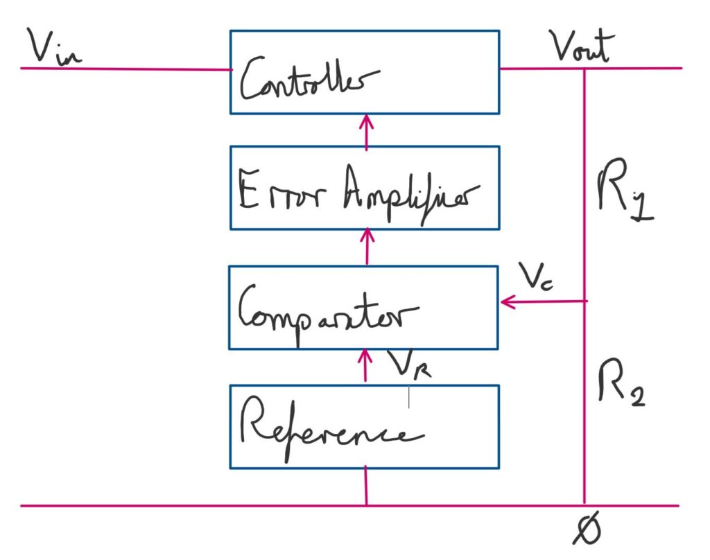
Together, the system tries to keep Vc equal to Vr, and therefore Vout constant, no matter what happens to Vin. Though there are limits to how much variation it can handle. In this system

Vc=VoutR2R1+R2

And since Vc = Vr

Vout=VrR1+R2R2

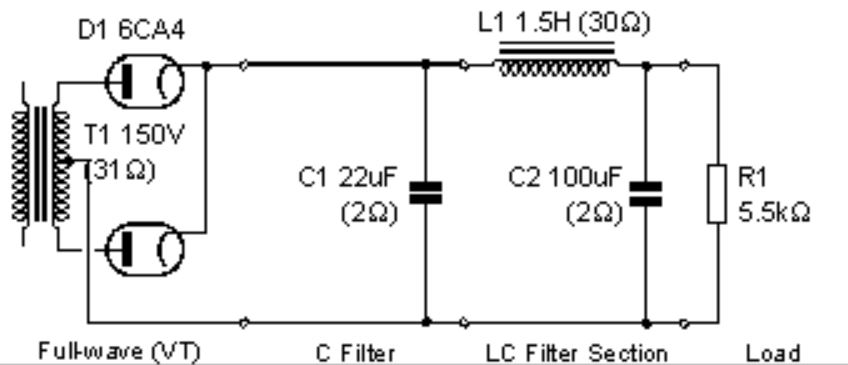
We have the reference voltage – it is a VR tube. What about the other three? The comparator and error amplifier are one device – in this case a triode. The controller (usually called the series pass tube, or just the pass tube, in this toplogy) could also be a triode. This diagram, from a 1947 issue of Radio magazine, illustrates the components nicely, leaving out various supporting resistors and capacitors:

High-level regulated power supply design

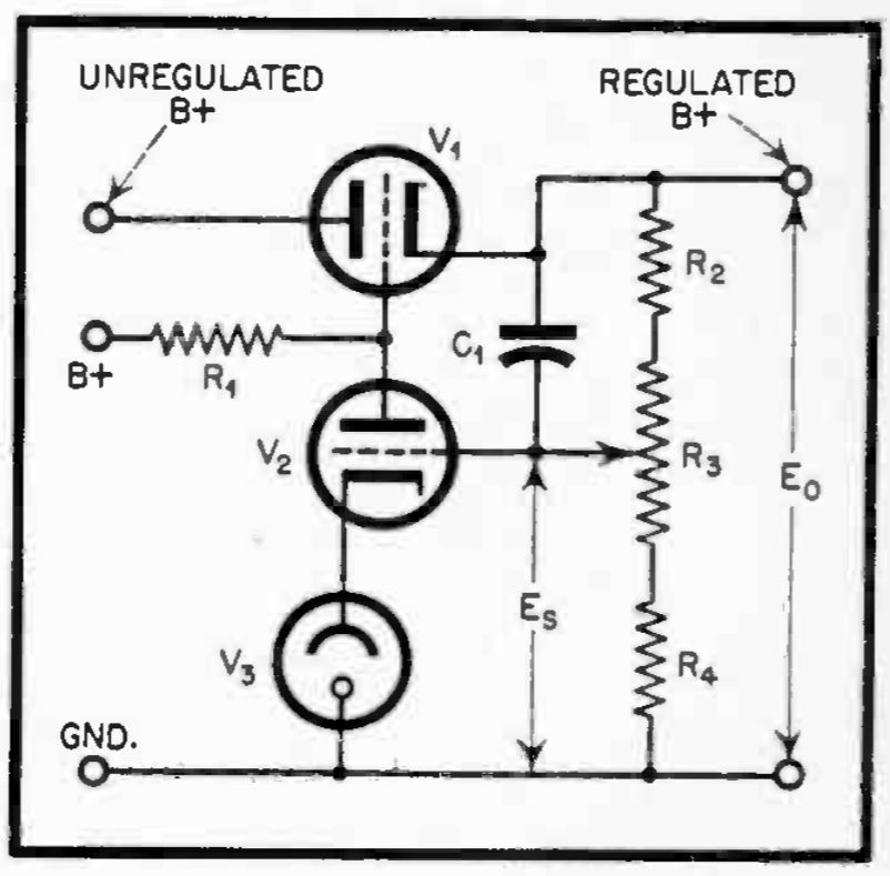
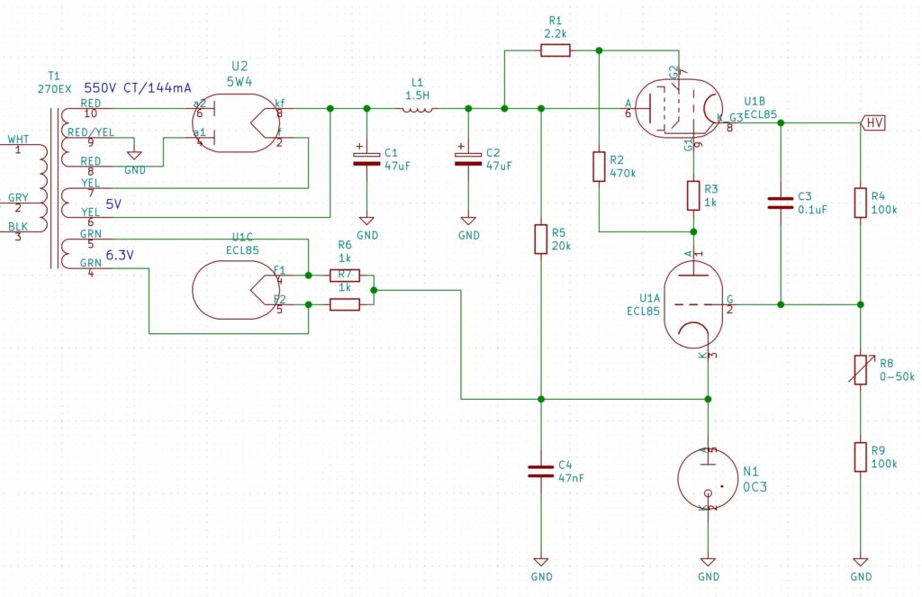
However, I will use a pentode for the pass tube, because I’m going to use a single tube that contains both a triode and a pentode – the ECL85 (aka 6GV8). The VR tube will be a 0C3, because it is a 108V VR tube and it looks nice!

As it turns out, the ECL85 also has a 6V3 heater, but it needs it to be at a potential that is within 100V of either cathode. That means I can’t use the same 6V3 transformer winding for both the ECL85 and the rectifier tube. In addition, there is significant voltage drop across the pentode and the whole thing will need more current to drive it, so it was time to look for both a new transformer and a new rectifier tube. I ended up going with the 5W4G, which still has a reasonable forward voltage drop and can handle the additional voltage and current. In addition it has a 5V heater which works well in this setup, because transformers that have one 5V and one 6V3 winding are more common than transformers that have two 6V3 windings. For the transformer, I settled on another Hammond, the 270EX.

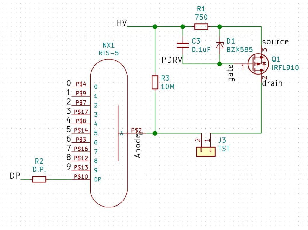
The 5W4G has a directly heated cathode, unlike the 6CA4, which means that it is at the same potential as the cathode. So now I have a problem. Both the 5V and the 6V3 windings are at different potentials than the main secondary winding, which means I can’t use either of them for my 5V supply, at least directly, as my 5V supply needs to share a 0V rail with the main secondary. I’ll come back to this later – I want to talk about the control circuitry first. I’ll finish this post with the final circuit diagram of the power supply:

Final Regulated Tube Power Supply

Nixie Clock With Vacuum-tube Power Supply – Part 2

In Part 1 I covered the genesis of this project and my first stab at a vacuum tube power supply.

One of the things I wanted to do was provide all of the power for the clock from the transformer. My regular clock circuit only needs 5V, so I figured I could get this from the 6V3 filament winding using a bridge rectifier and a 5V voltage regulator. This is only really possible because the 6CA4 rectifier tube uses an indirectly heated cathode. That is to say, the heater is not connected to the output pins, so it can be at any potential with respect to the output voltage. In particular, it means we can tie one side of the heater to the common ‘ground’ or 0V rail. The HV ‘ground’ is the center tap of the secondary:

Circuit, showing heater

Some of you may have figured that that is cutting it a bit too fine. A bridge rectifier using regular diodes could drop around 1.4V to 2V depending on the current draw. The voltage regulator would drop another 2V, so it needs a steady 7V in. So if the smoothing were perfectly efficient, we would go from 8.9V (6.3*1.414) to possibly less than 7V. Simulation with LTSpice shows this is optimistic.

Another alternative would be to use Schottky diodes for the bridge, and simulation show this would probably work. However, I decided to use a simple voltage multiplier on the 6V3 AC which gives me better smoothing for fewer components. So the whole circuit now looks like this:

Circuit with 5V section

You’ll note that this diagram is slightly different. I have cut the direct connection between pin 4 of T1 and the 0V rail of the HV section. Instead I have explicitly shown each section (the voltage doubler, HV and 5V sections) with a separate connection to ground. This is because, as it is, I am only using one half of the voltage doubler. This is just one diode drop, rather than two (as with the a full-wave bridge), so the voltage is enough for the 7805 regulator. If I wanted to use the full doubled voltage, I could just move the voltage-doubler ground to the point labelled A instead.

This is all very well, but it turns out to have a couple of draw-backs, as will become apparent later.

Current Limiter

The HV power supply is unregulated – which is to say, as you draw more current, the voltage starts to sag. This is because the forward voltage drop of a rectifier tube increases as the current increases. To get around this I decided I would use a small constant-current circuit to drive my Nixie tubes, in place of the usual current-limiting resistor. This basically works by connecting the source of a PMOS transistor to HV via a resistor (Rset) and then biasing the gate a fixed voltage below HV (Vgs) like so:

This is the equation for the resistor, given the desired current (Id):

Rset=VgsVgs(on)Id

Where Vgs(on) is the voltage drop between the source and the gate, which you can get from the transfer characteristics chart of the data sheet. A rough estimate would the typical gate threshold voltage.

Of course, the trick is to keep Vgs constant, even though HV is varying. To this end, I used a small isolated DC-DC converter to boost 5V to 12V and then attach it to the circuit as shown above. The gate takes virtually no current, so the boost converter can be very small. Using a voltage divider let’s us get to 10V and using a small potentiometer in one leg of the voltage divider allows us to adjust the voltage to get precisely the current we want.

Following some advice I received on the Neonixie google group, the actual circuit is a little more complicated, to provide some protection to the MOSFET. I designed some boards to act as sockets for the nixie tubes that included all this circuitry:

At this point I had decided I would ultimately want to use all of this to build a clock that would feature the large NL7037 tubes I had been collecting. I had been meaning to build a clock with an industrial feel to it to match the look of these tubes, and I felt that this would be the one. Finally here is a shot of a test I made using one of the tubes and adapters:

Nixie Clock With Vacuum-tube Power Supply – Part 1

About 7 months ago, I watched a video by glasslinger about adding a nixie tube display to a vintage radio. This was something I had wanted to do for a while, but I didn’t know how to read the tuned frequency from the radio. There were many interesting parts to the video (I recommend you watch it), but one of the things I learned was that vacuum tube radios that had tranformers, actually generated voltages with those transformers that were high enough to drive Nixies.

I spent a little while trying to find a radio with an input transformer like that, and in the meantime, I started researching vacuum tube power-supply design. That was when I finally realized that these things were still being made for guitar (and HiFi, but especially guitar) amplifiers. So you could actually buy new transformers and new vacuum tubes and new chokes that you could use in a new power supply. That is when I got really serious about this.

At this point, two sites influenced my initial design. The first was ‘Fun With Tubes’, which had several simple designs. The second was ‘DIY Audio Projects’. which went in to much greater depth about tube selection and circuit calculations. In particular, the latter had a nice chart showing the voltage drop that different vacuum rectifier tubes had. Some of them were quite startling – for example the 5Y3, used by the first site, had a voltage drop of almost 45 volts for a plate current of 100mA, compared with only 15V for the 6CA4. What’s more, the 6CA4 is still in production.

The DIY Audio projects site showed a long series of manual calculations to determine properties of that simple un-regulated power supply. I entered these in a spreadsheet to make life easier, however, I later found a little application called psud2 (power supply designer 2) that did the same thing using a simulator and a few values from the data sheets. The important thing being that the maximum 6CA4 plate current (which is on a cold start) does not exceed the maximum allowed plate current on the data sheet.

Taking a hint from the DIY Audio Projects page, I decided to go with a one-stage choke filter to smooth the output of the rectifier tube. Confusingly (for me) everyone refers to this as the ‘input filter’. I guess because it is the input to whatever comes after this stage – usually an amplifier. So this is what I ended up with (from dsud2):

Unregulated vacuum tube power supply

Obviously(?) this is just the output stage. On the input side is 125V 60Hz, a 1A slow blow fuse in the hot line and a neon indicator across hot and neutral, so I could tell when it was on.

Something I omitted was a resistor to drain the capacitors when power was removed. Those capacitors can hold a charge for a long time. I soon added one. Experience is wonderful thing.

Here is a chart from psud2 showing the expected output:

Power supply simulation

The next stage was to select some actual components and bread-board it. I ended up going with a 269BX transformer from Hammond, a 156R choke (also from Hammond) and a new 6CA4 from JJ Electronics. All the rest are just suitably spec’d parts from DigiKey and a bunch of terminal strips, screws, fuses, switches, fuse holders etc. from my local electronics store.

I would show you a picture of the breadboard, but I will save that for part 2, when I discuss how to deal with the potential for voltage sag.