I’ve used the KRC-86B bluetooth module in several projects. It is tedious trying to figure out which one I am about to connect to, because they all have the same name, so it would be great to be able to rename it. It would also be nice if the name meant something.
This is a summary of this instructable. Things have changed a little since it was written, so this little post summarizes the state of play at the moment. It is still well worth watching the video in the instructable and reading the comments.
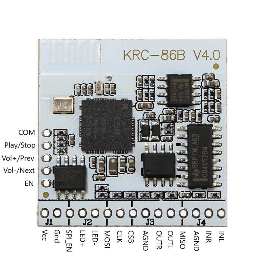
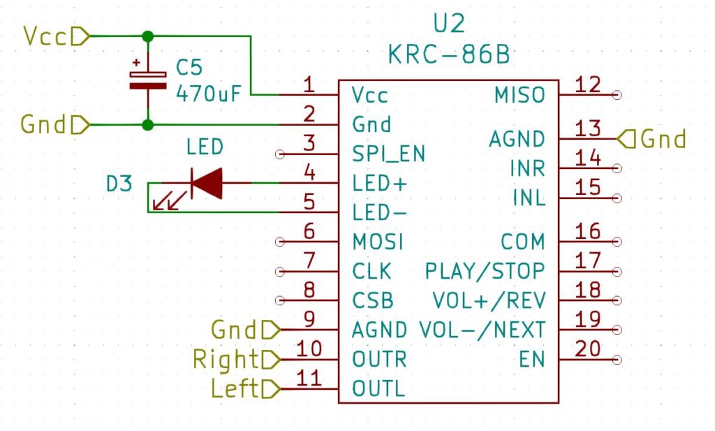
To rename the module you need to modify one of the settings stored on it. This is done using the SPI interface that is part of the module. I’ve documented the pins in the image below – on the module itself they are marked as NC.
KRC-86B bluetooth module pin assignments
So all you have to do is to send commands over SPI! This might sound a little daunting, but actually it is quite simple. The CSR8630 chip on the module was developed by Qualcomm, and they developed windows software to do the heavy lifting. The software is called BlueSuite. Qualcomm no longer provide this, but you can get multiple versions here. You should use the latest version there, which is bluesuite.win.2.6_installer_2.6.11.1937.zip.
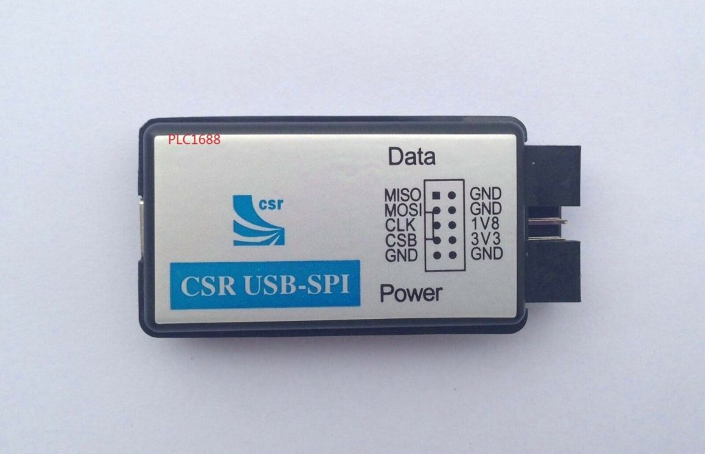
Next you will need a USB to SPI converter. I used this one:
PLC1688
You will need to figure out some way to attach this to the KRC-86B. Check the actual pinouts on whatever USB adapter you use.
Install the BlueSuite software.
Connect the 3V3 pin to Vcc on the module
Connect a 10k pullup resistor between Vcc and SPI_EN to enable the SPI interface on the module.
Connect MISO to MISO, MOSI to MOSI, CLK to CLK and CSB to CSB.
Plug the PLC1688 (or whatever) into your PC.
Run pstool (which is what is installed by the BlueSuite installer). It should detect the module and you can just hit OK. If it doesn’t detect it, troubleshoot your connections.
Make a backup of the module – File>Dump
Search for name
Change it
Check it changed to what you want using your phone
And that is it. Pretty simple.
Many thanks to sjowett. I spent years searching for this.
I’m writing this as much for my own use as anything else – I keep having to re-invent this solution every time I fix a vintage radio.
Most vintage radios are AM only, and in my part of the world, the only thing on AM is talk radio. Even if that weren’t the case, let’s be honest, most of what people listen to these days is streamed. I don’t like my radios to be shelf-queens, I want to be able to use them and honestly, the sound from the bigger radios is great.
One solution to this is to add an aux-in so that you can plug in an external source and play it through the radio. this certainly works (and you can use most of what is here to do that), but you still need a Bluetooth dongle and leads, and you have to charge it up and turn it on and switch the radio to aux-in. This solution wires the Bluetooth ‘dongle’ into the radio directly, so that it comes on when the radio comes on.
Overview
This shows a high-level view of what we are going to do:
Bluetooth Mod Overview
Radio Modifications
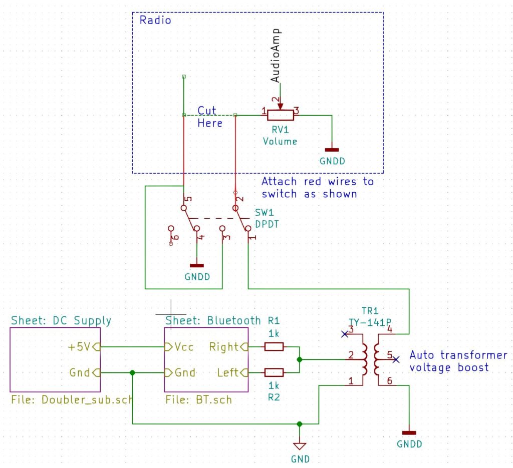
Let’s look at the radio block first. The modification here is the same regardless of what external source we are going to wire in. We are going to wire our new audio source across the volume control.
Find the lead going to the volume control that is not connected to ground and does not go to the audio ouput stage. we will cut this wire and route it to a double-pole double-throw switch. A double-pole double-throw switch is simply a switch with two positions (double-throw) that switches two sources at the same time (double-pole). In one position the switch will connect that wire back to the volume control. In the other position it will connect our new audio source instead.
NOTE: It is a good idea to use shielded cable to make the connections between the radio and the switch. Connect the shield to chassis ground.
In the diagram above you can see (hopefully) that when our new audio source is connected, the original one is connected to ground rather than just left floating. This helps stop sound from the RF/IF stages of the radio from bleeding through to the speaker.
Bluetooth Module
The next block to look at as the one marked Bluetooth. You will see that the right and left channels are connected together via two 1k resistors. The use of these resistors prevents the output from one channel destroying the other channel.
Transformer
The next block we will talk about is the auto-transformer. This can serve two purposes.
The first is to boost the output of the Bluetooth module so that it has about the same loudness for a given volume setting as the radio itself. The particular model I am using is the TY-141P. If it is wired as shown in the diagram it gives a 1:2 voltage boost, which seems about right on all the radios I have modded. Triad make another transformer – the TY-142P that can give a boost of 1:2.24 or 1:4.48 depending on how it is wired.
The second purpose is that it can act as an isolation transformer to decouple the new audio source from the radio. This can help to remove ground-loop hum that can arise depending on how the new source is powered. In some scenarios, the chassis ground (GNDD) may be the same as the power supply ground (GND).
NOTE: The point that the auto-transformer is connected to chassis ground can be important. I have found that if you connect it to the volume ground terminal, you will hear hash from the Bluetooth receiver when listening to broadcasts. Experiment with different locations. If all else fails, use a three-pole double-throw switch to disconnect the power to the Bluetooth unit when listening to broadcasts.
Bluetooth Module Details
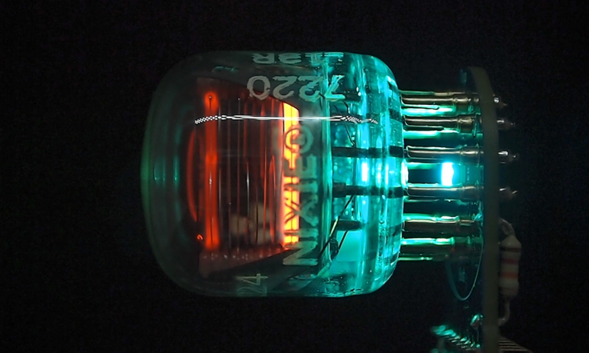
My preferred Bluetooth module is the KRC-86B, pictured below:
KRC-86B Bluetooth Module
There are a lot of possible connections that we aren’t going to use. We are just going to provide it with a Vcc of +5V and use OUTL and OUTR like so:
KRC-86B Connections
The LED indicates the state of the module. If it is connected it will be steady. If it is not connected it will be flashing, and if there is no power, it will be off! The capacitor is just a decoupling capacitor. Both of these are normally provided with the module.
Power Supply Details
The KRC-86B needs 3.7V to 5V. You could provide this with a battery pack or an external 5V supply and you could wire this power source in to the switch so that it only powered the module when it was selected as an input, but you would need a three-pole double-throw switch to do that.
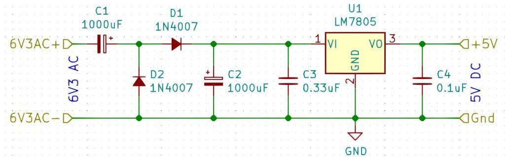
The module only draws at most 80mA, so let’s see if we can provide that directly from the radio. We will probably need to convert some AC voltage into a DC voltage. Some radios have a transformer that provides the filament voltage, and these are probably the cleanest way to power the device. We can just convert the 6.3V AC into 5V DC. Another alternative I have used is to connect my power supply in parallel with the filament of a vacuum tube.
The basic idea is to rectify the AC, smooth it and then feed this through a 5V voltage regulator. 8V-12V is ideal for using a bridge rectifier, however 6.3V won’t provide a high enough rectified and smoothed voltage to feed a 5V voltage regulator, so in this case we need to use a voltage doubler as in the circuit below:
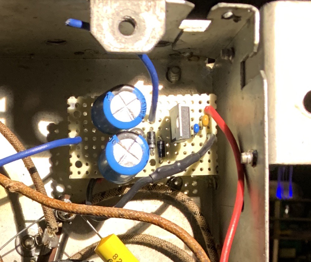
Here’s what it looks like. In this case, there was a handy post I can screw it to:
5V DC Power Supply
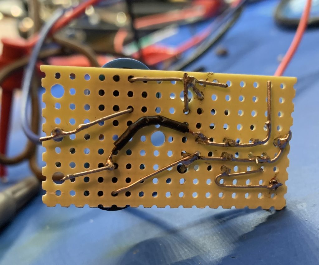
This is what it looks like underneath:
Some nifty point-to-point wiring
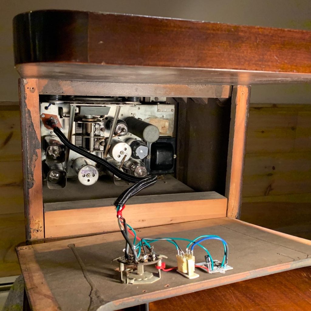
Finally, here is what the module, switch and auto-transformer look like in one of the radios I modded. In this case the switch was already there from a mod that had been made in the dim and distant past:
Bluetooth mod installed in a Philco 38-7 chairside radio
I have made several nixie clocks built around the ESP32. They incorporate a speaker, and I thought it would be nice if I could also stream music to them. The ESP32 has built-in Bluetooth support, so I figured I should try and use that first – essentially turn the clocks into a Bluetooth speaker.
I set about looking for examples and rapidly discovered that this was a little-used feature. Almost all the coding examples on the internet focus on Bluetooth BLE. I needed to use Bluetooth A2DP. Furthermore, I needed to implement an A2DP sink – that is something that audio data is sent to rather than from.
All of the code I could find was very low level and hard to understand – it would have been hard to incorporate it into an existing code base. It was all written in C, had zero encapsulation and seemed to be littered with code that was unnecessary for what I was trying to achieve.
To cut a long story short I wrapped it all in to some C++ classes. There are four main classes:
Audio
DataSink
EventSink
Out
Audio
This class just initializes the bluetooth protocol stack.
DataSink
This class listens for audio data and writes it to a ring buffer.
EventSink
This class listens for A2DP lifecycle events such as connected, suspended, configure etc. and publishes the events to any objects that subscribed to them.
Out
This class reads the audio data from the ring buffer and streams it out to an external DAC connected to the I2S ports.
The code is here. It can be used with or without the ESP32 Arduino framework. There is an example that uses the Arduino framework in the repo.
In the end I’m not using it with my clocks. All the code together blows the heap allocation and requires me to use a different memory layout. I might look in to sorting that out later.