Adding Bluetooth to a Vintage Radio

I’m writing this as much for my own use as anything else – I keep having to re-invent this solution every time I fix a vintage radio.

Most vintage radios are AM only, and in my part of the world, the only thing on AM is talk radio. Even if that weren’t the case, let’s be honest, most of what people listen to these days is streamed. I don’t like my radios to be shelf-queens, I want to be able to use them and honestly, the sound from the bigger radios is great.

One solution to this is to add an aux-in so that you can plug in an external source and play it through the radio. this certainly works (and you can use most of what is here to do that), but you still need a Bluetooth dongle and leads, and you have to charge it up and turn it on and switch the radio to aux-in. This solution wires the Bluetooth ‘dongle’ into the radio directly, so that it comes on when the radio comes on.

Overview

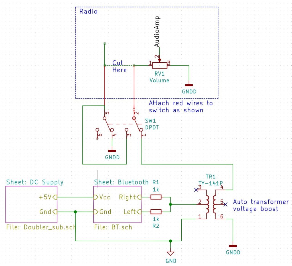
This shows a high-level view of what we are going to do:

Bluetooth Mod Overview

Radio Modifications

Let’s look at the radio block first. The modification here is the same regardless of what external source we are going to wire in. We are going to wire our new audio source across the volume control.

Find the lead going to the volume control that is not connected to ground and does not go to the audio ouput stage. we will cut this wire and route it to a double-pole double-throw switch. A double-pole double-throw switch is simply a switch with two positions (double-throw) that switches two sources at the same time (double-pole). In one position the switch will connect that wire back to the volume control. In the other position it will connect our new audio source instead.

NOTE: It is a good idea to use shielded cable to make the connections between the radio and the switch. Connect the shield to chassis ground.

In the diagram above you can see (hopefully) that when our new audio source is connected, the original one is connected to ground rather than just left floating. This helps stop sound from the RF/IF stages of the radio from bleeding through to the speaker.

Bluetooth Module

The next block to look at as the one marked Bluetooth. You will see that the right and left channels are connected together via two 1k resistors. The use of these resistors prevents the output from one channel destroying the other channel.

Transformer

The next block we will talk about is the auto-transformer. This can serve two purposes.

The first is to boost the output of the Bluetooth module so that it has about the same loudness for a given volume setting as the radio itself. The particular model I am using is the TY-141P. If it is wired as shown in the diagram it gives a 1:2 voltage boost, which seems about right on all the radios I have modded. Triad make another transformer – the TY-142P that can give a boost of 1:2.24 or 1:4.48 depending on how it is wired.

The second purpose is that it can act as an isolation transformer to decouple the new audio source from the radio. This can help to remove ground-loop hum that can arise depending on how the new source is powered. In some scenarios, the chassis ground (GNDD) may be the same as the power supply ground (GND).

NOTE: The point that the auto-transformer is connected to chassis ground can be important. I have found that if you connect it to the volume ground terminal, you will hear hash from the Bluetooth receiver when listening to broadcasts. Experiment with different locations. If all else fails, use a three-pole double-throw switch to disconnect the power to the Bluetooth unit when listening to broadcasts.

Bluetooth Module Details

My preferred Bluetooth module is the KRC-86B, pictured below:

KRC-86B Bluetooth Module

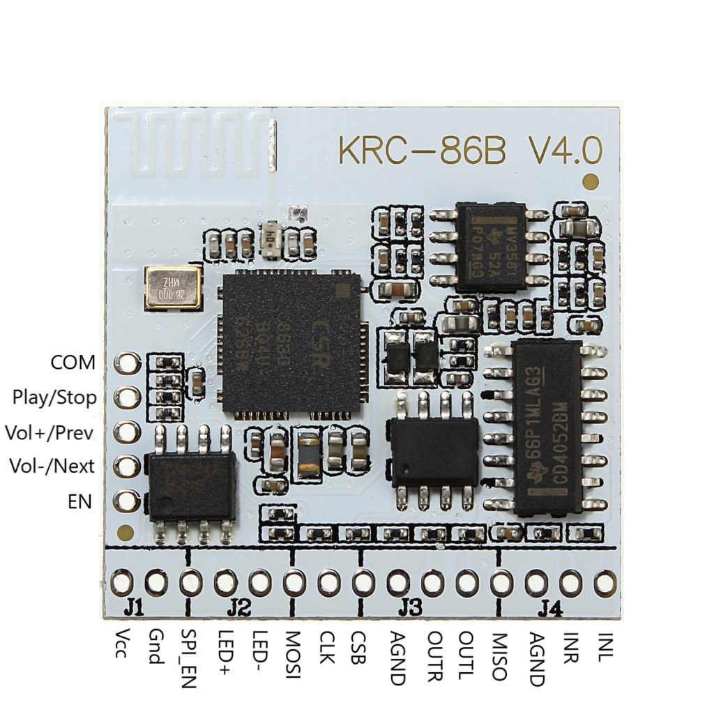
There are a lot of possible connections that we aren’t going to use. We are just going to provide it with a Vcc of +5V and use OUTL and OUTR like so:

KRC-86B Connections

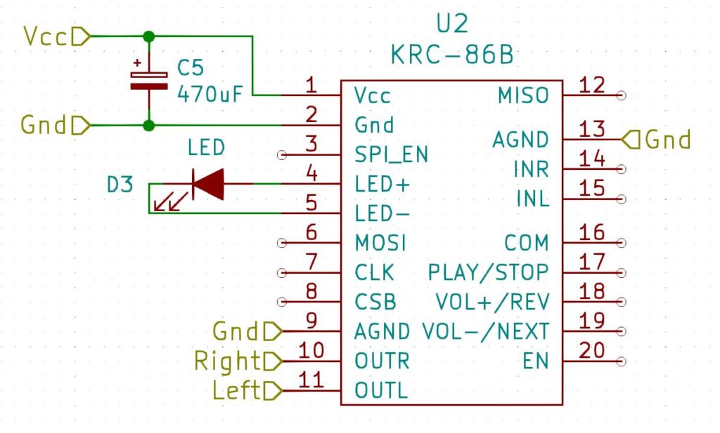
The LED indicates the state of the module. If it is connected it will be steady. If it is not connected it will be flashing, and if there is no power, it will be off! The capacitor is just a decoupling capacitor. Both of these are normally provided with the module.

Power Supply Details

The KRC-86B needs 3.7V to 5V. You could provide this with a battery pack or an external 5V supply and you could wire this power source in to the switch so that it only powered the module when it was selected as an input, but you would need a three-pole double-throw switch to do that.

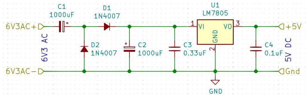
The module only draws at most 80mA, so let’s see if we can provide that directly from the radio. We will probably need to convert some AC voltage into a DC voltage. Some radios have a transformer that provides the filament voltage, and these are probably the cleanest way to power the device. We can just convert the 6.3V AC into 5V DC. Another alternative I have used is to connect my power supply in parallel with the filament of a vacuum tube.

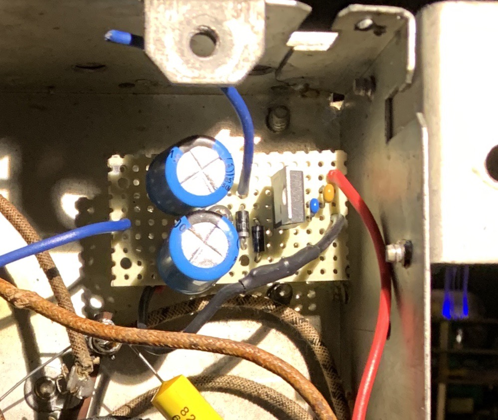
The basic idea is to rectify the AC, smooth it and then feed this through a 5V voltage regulator. 8V-12V is ideal for using a bridge rectifier, however 6.3V won’t provide a high enough rectified and smoothed voltage to feed a 5V voltage regulator, so in this case we need to use a voltage doubler as in the circuit below:

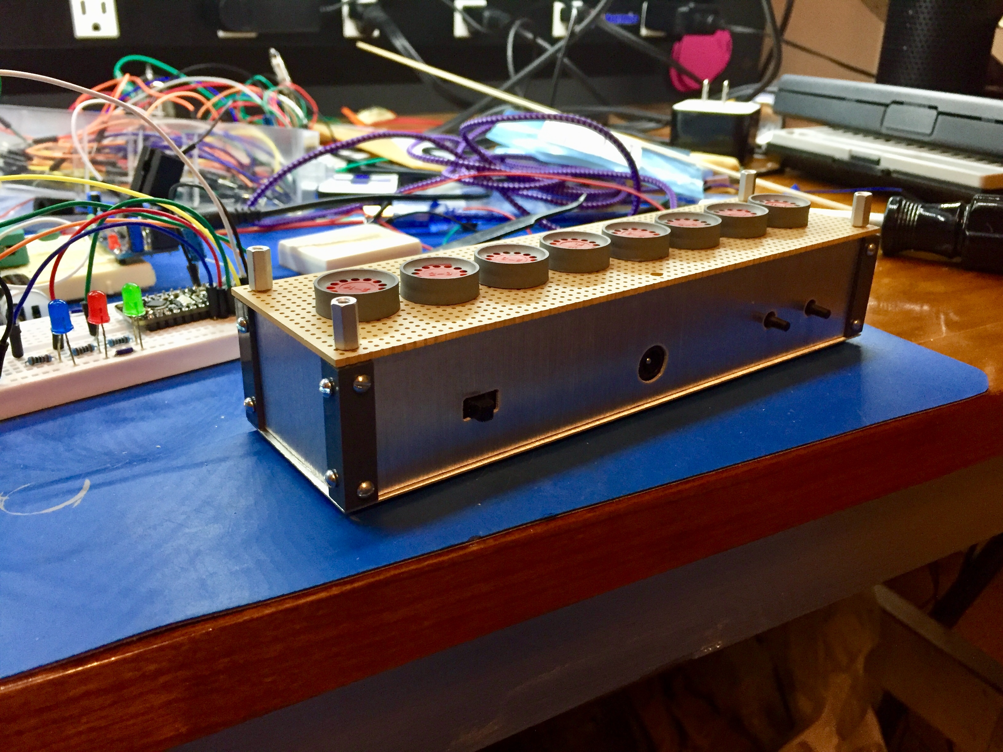
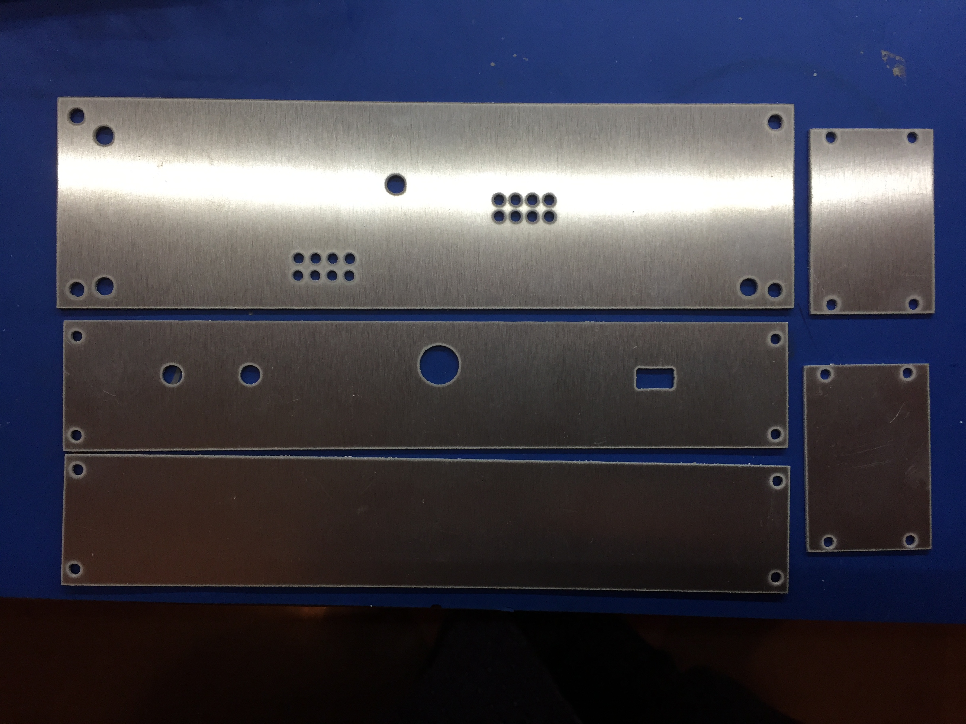
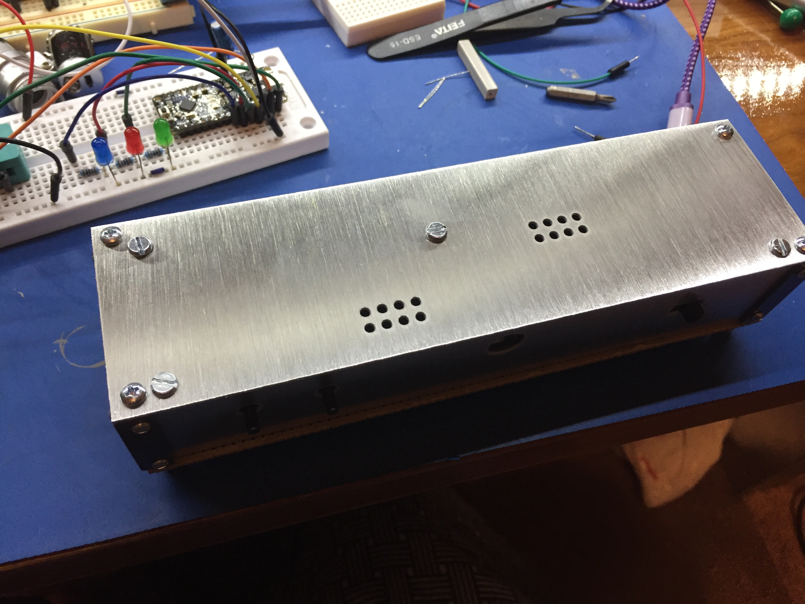
Here’s what it looks like. In this case, there was a handy post I can screw it to:

5V DC Power Supply

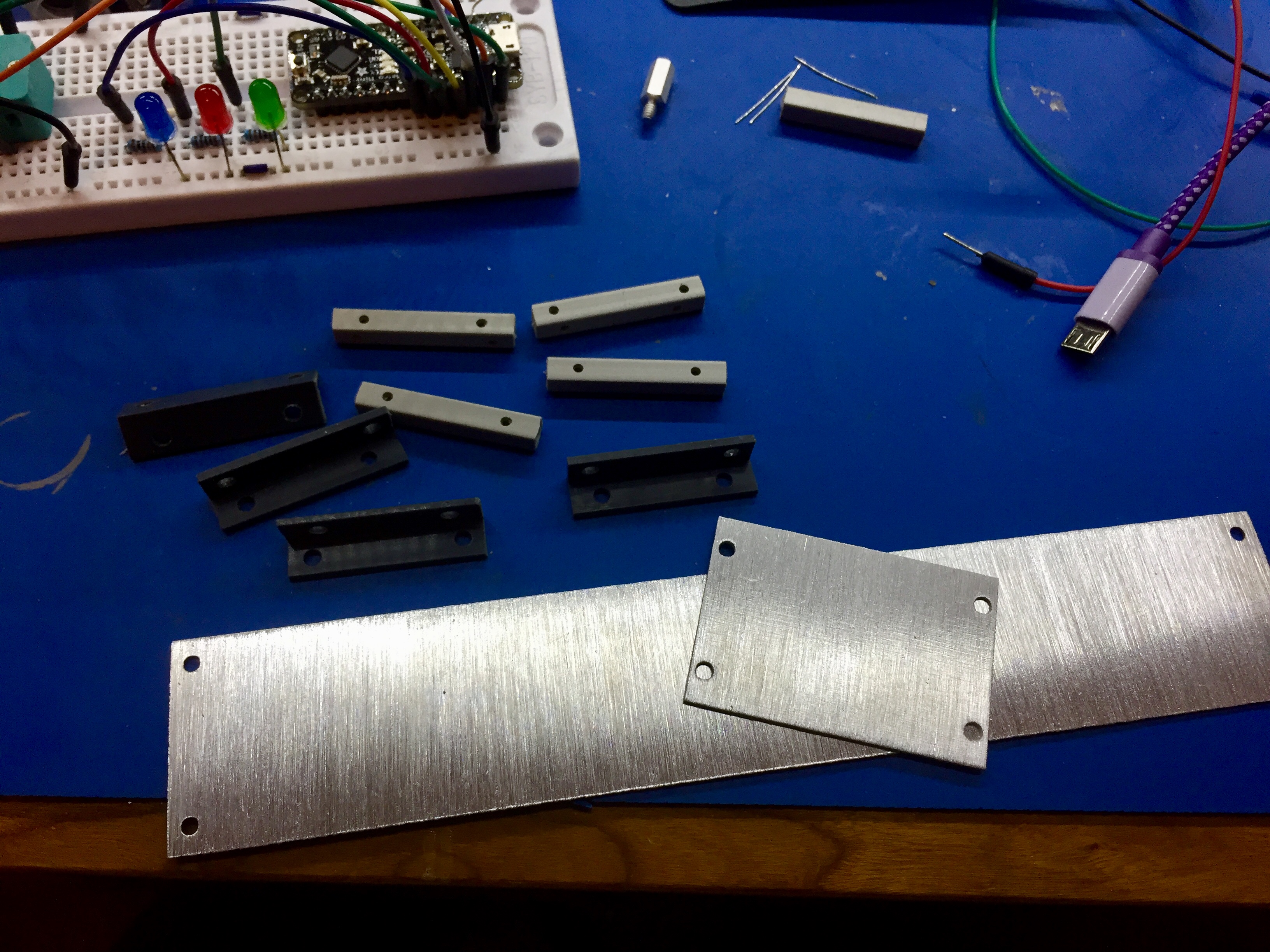
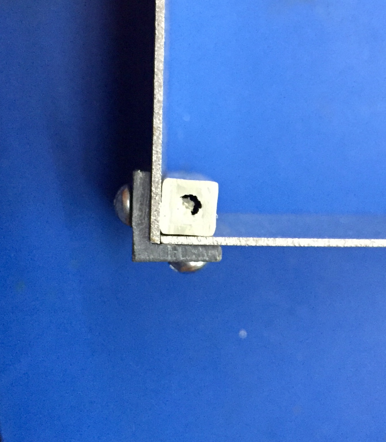
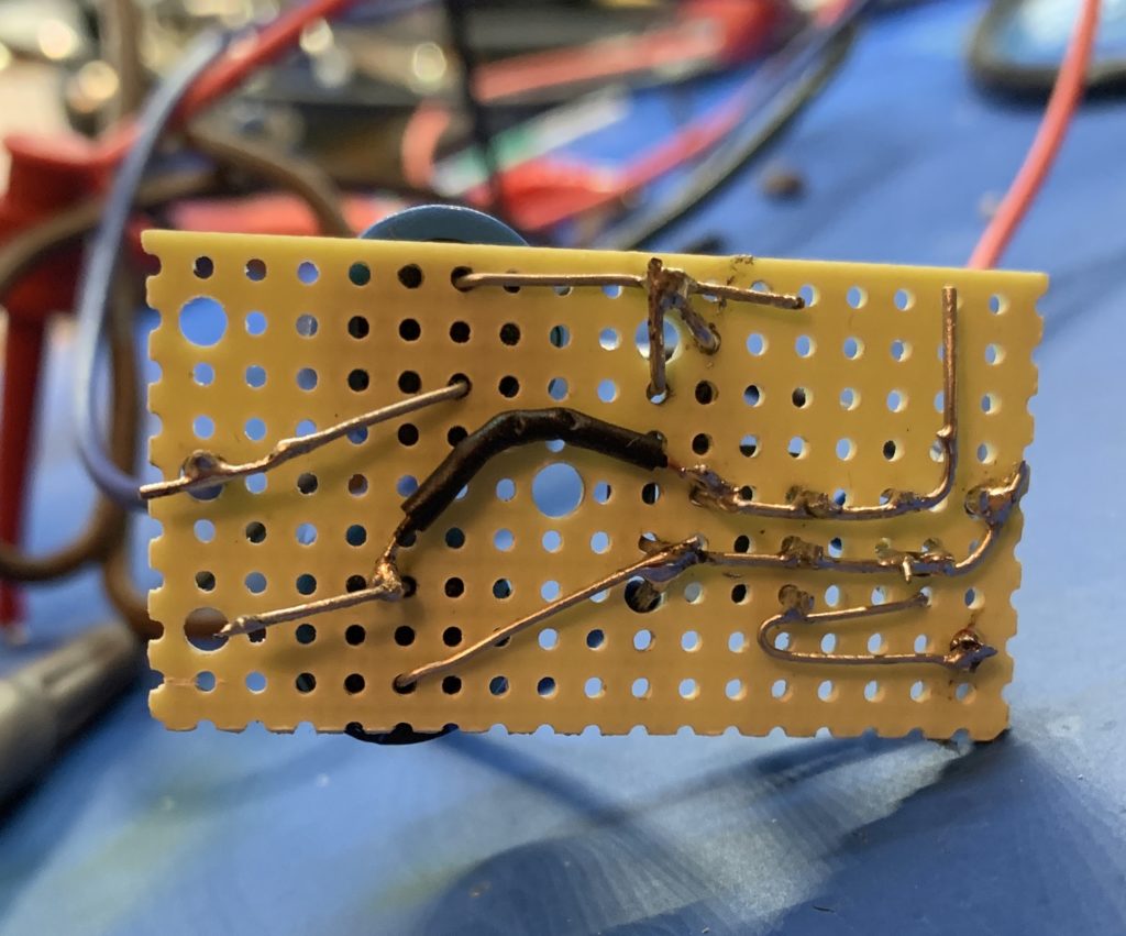
This is what it looks like underneath:

Some nifty point-to-point wiring

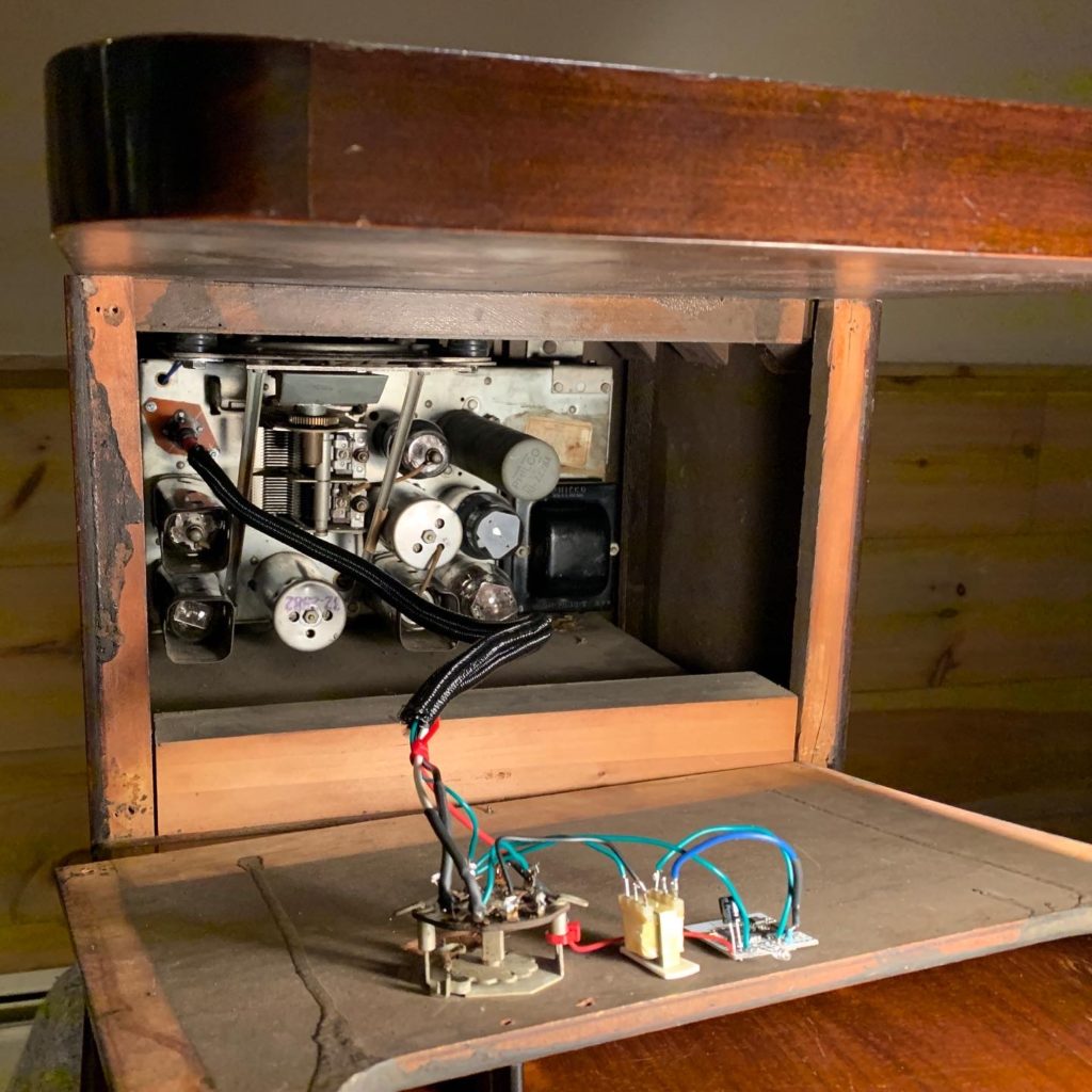
Finally, here is what the module, switch and auto-transformer look like in one of the radios I modded. In this case the switch was already there from a mod that had been made in the dim and distant past:

Bluetooth mod installed in a Philco 38-7 chairside radio

Nixie Clock With Vacuum-tube Power Supply – Part 4

This is the fourth post about a nixie clock project that is powered by a vacuum tube power supply, rather than the more common 12V or 5V wall wart. The previous part can be found here. I’m going to take a break from talking about the power supply and veer off into talking about the controller hardware.

One of the features I had wanted to add to a nixie clock for some time was to simulate the ticking noise of a mechanical clock. To that end, I had previously bought an ESP32 Pico dev kit (because it support I2S), but then done nothing with it. It was time to resurrect that idea. By the way, the reason for choosing the Pico was that the chip itself requires the minimum of additional hardware to build my own PCB using the chip.

Now that I was seriously developing for the ESP32, I actually delved deeper into the software platform and discovered that it is running RTOS. This is a real time operating system with support for multiple prioritized tasks. In fact, the ESP32 arduino platform uses a single RTOS task to implement the loop() callback. My code for the ESP8266 basically split the work in the loop() method into multiple tasks, so I figured I could drop all the scaffolding I had written to do that, and just use one RTOS task on the ESP32 for each task that I wanted the ESP32 to complete (the clue is in the name!), rather than stuffing a bunch of calls into the loop() method.

The first thing I wanted to play with was playing sounds – that was the whole point of considering the ESP32 for the core processing. I started by looking around for libraries that I could use to play sounds and settled on ESP8266Audio which, despite the name, has good support for the ESP32. For it to be useful, I also needed to buy a SD Card reader module and an I2S amplifier module, both of which are available from Adafruit.

One advantage of the ESP8266Audio library is that it uses DMA to feed the data to the I2S pins of the ESP32. So theoretically, user code just has to keep the DMA buffer full, and then the data is pushed out of the pins via interrupts. It seemed like this would be the right thing to do as I was going to be loading up the processing to handle more and more tasks. I initially had trouble with the sound glitching. It was difficult to tell if this was because of the software or the breadboarding I was doing. As I added more tasks the glitching got worse. In the end it was easily fixed by increasing the DMA buffer count from 8 to 64!

The next task I wanted to add was driving neopixels. I had tried this before on the ESP32 with little success. It tended to be very glitchy. Looking around I discovered another library called NeoPixelBus which, like ESP8266Audio, could use DMA to feed data to the NeoPixels. Fortunately there are two DMA channels on the ESP32 and also fortunately, I could tell the libraries which one I wanted them to use. However, the neopixels would still occasionally glitch. At this point I wasn’t sure if this was because of my breadboarding or the software, so I chose to ignore it. It turns out that there is a bug in the ESP32 DMA firmware. NeoPixelBus changed their default support to use the IR remote support, but I still found that it glitched occasionally. Finally, when I upgraded the Arduino platform to v1.0.4, the glitching stopped.

Next I needed to drive the Nixie tubes. I implement fading and cross fading all in software, so I need better timer resolution than can be provided by the task manager. So I implemented this in an interrupt routine. I had already done this for the ESP8266, so I was familiar with the need to decorate all interrupt methods so that they would reside in IRAM. However it turns out that that wasn’t enough.

Firstly, my interrupt code is in C++ and uses virtual functions. It turns out that for the ESP32, the compiler is putting the v-tables in flash, so I had to resort to copy/paste and get rid of all of the virtual functions. BTW, the version of the ESP8266 platform I was using was storing the v-tables on the heap. Later versions allow you to specify where the v-tables are stored. It would be nice if the ESP32 platform did the same.

It still crashed, and I eventually discovered that g++ was generating function calls to do long division. That function is not in IRAM. The millis() function (which is in IRAM) uses long division. I guess no one had ever called it from an interrupt routine before? Thankfully the developers changed the default compiler flags to inline the code instead. So all was good.

Next I wanted to use a WiFi manager library to handle setting up the connection to a router. Thankfully, the one I prefer to use – ASyncWiFiManager was also the only one that had been ported to the ESP32. However, my iPhone simply would not connect to the access point – my laptop had no problem. Turns out that there was a bug in the ESP32 core which was fixed just after I discovered the issue. An aside: this is interesting, I am pretty sure the ESP8266 core has a similar problem, as connecting to the AP from an iPhone is patchy on the ESP8266.

So then I was implementing my Web GUI, which uses the SPIFFS library to store the assets. That’s when I discovered that the SPIFFs library on ESP32 was broken. So I fixed that and the fix was incorporated into the Arduino core.

So finally, everything that I needed (software wise) worked great and has, in fact, been extremely stable.

Complete Divergence Meter

I’ve been building a Divergence Meter, as featured in Steins;Gate, using Tom Titor’s excellent design.

Perfboard

If you’ve read any of my other posts about this project, you’ll know that I hit some obstacles. First I blew up the HV power supply and the PIC chip, then the perfboard I had, had logos printed on both sides. Well I replaced both the power supply and the PIC chip. As for the perfboard, I couldn’t find any that was the right size, the right color and logo-free. In the end I followed a suggestion and spray-painted it. Here’s a before and after shot:

Before and after spray painting

That particular piece wasn’t cut very well, so I used it for practice. To cut the perfboard, I used a technique recommended by a carpenter friend. If you use a saw it is hard to get a clean edge, so I used a router instead. Here is the setup I used:

Router Jig

Case

And that is pretty much where I stopped for a while – I still hadn’t figured out how I was going to build the case. I played around with prototypes made out styrene sheet, and while I was doing that I realized that the hex standoffs used to hold the top to the case screwed easily into the plastruct rod I was using to brace the corners – it has a round hollow core:

Plastruct rod test 1

And then it suddenly occurred to me that I could drill pilot holes in the rod, and use self-tapping screws to fix the sides of the case to the rod. I tested it on some aluminum sheet I had, and it worked really well. So now all I had to do was CAD it up and get it made by Big Blue Saw. Here is a shot of the end result:

Case from the back

Drilled plastruct and some of the case parts.

I had also decided that the PCBs inside the case needed some good support, so I used 11/16″ plastic standoffs to mount the main board to the case. It needs to be this length to accommodate a 9V battery. By my calculations that meant I also had to increase the height of the case slightly, so I did.

Construction

Now I knew everything would go together I could get on with the rest of the construction. Here are a few progress shots:

Gluing the dummy components

Soldering in the tubes

For some extra veracity, I used a busted 7441 chip and a busted К155ИД1 chip for the dummy ICs:

ITT 7441 dummy IC

К155ИД1 dummy IC

I discovered that the gloopy super glue I was using (aka CA Adhesive), really didn’t want to cure. Tom had mentioned that it would be useful to have some accelerant, and I guess it is. Googling CA glue accelerator shows it is just a mild alkaline solution that neutralizes the acid used in the glue, to slow down curing. I found this article about how to make your own, so I did and it worked great.

Software

The programmer in me couldn’t leave the code alone, so I modified it a little. There are two main changes:

  1. The wordline modes will automatically go on to the next wordline after about 9s, unless a button is pressed.
  2. In clock mode, it will display a random world line twice an hour.

I uploaded the source and a hex file to GitHub.

Finished Clock

Finally, here’s a shot of the finished clock:

World Line Display

Divergence Meter Setbacks

Firstly, I only ordered one push-button instead of two. Annoying, but not a big deal.

Secondly, the perfboard had logos printed all over it. No chemical would get them off. Sanding didn’t get them off. When I used a dremel, I discovered the pigment went deep into the substrate. I figured that maybe this was just the particular supplier that DigiKey was using, so I ordered some straight from the public BOM on Mouser. It is exactly the same. So I am down $34 on perfboard I can’t use.

Perfboard
Perfboard + Logos

I have ordered yet another perfboard for $23 from DigiKey from a different manufacturer. Hopefully this one won’t be covered in logos. So $57 on perfboard alone. So far!

Thirdly, I missed that the boards on OSH Park need an additional diode near the battery switch. Fortunately I had a suitable Schottky diode lying around.

Fourthly, when I was adjusting the HV it mysteriously stopped working, and the PIC started to get hot. I guess I shorted the HV to the PIC, though I don’t recall doing so. So I am down the HV and the PIC. The HV part is $14. The shipping is $10. So I am now down an extra $60 with little to show for it. Plus I had to unsolder the HV. Fun times!

Since there is little else I can do at this point, I built a prototype case with the styrene sheet. This is so I can test the positioning of the openings on the case before I get some metal ones fabbed.

Anyway, here are the boards, with a gaping hole where the power supply should be 🙁

Divergence Meter

Divergence Meter Kickoff

Its time to actually start building this divergence meter:

Divergence Meter Kickoff

I ordered the parts from Digikey, which have arrived. I chose to program the PIC16F628A myself, by which I mean upload the hex file from Tom Titor. Partly this is because I figure I might modify the program at some point. So I bought a cheap pickit 3 copy off ebay.

I’ve also been re-familiarizing myself with SolidEdge 2D as I would like to get the case pieces fabricated, so I will need an accurate CAD model, and I have used SolidEdge in previous projects.

In addition I have been mulling over how to actually build the case. Ideally I would like to make my own posts with a square cross-section and tap them for screws – I really don’t like the idea of gluing things together – however that is way beyond me at the moment. I also toyed with the idea of using styrene sheets  that are used in modelling. So in the end I bought samples of various materials and practiced gluing things together:

Practice pieces for the case

The top sheet is aluminum. The bottom sheet is steel. The left hand blob of glue is JB Kwik, the right hand blob is JB Putty. I glued some aluminum rod to the sheets with an overhang so I could try and pull them off. I roughed up everything with a dremel tool before hand and cleaned it all up with Isopropyl alcohol. In the end I was surprised how strong the bond made by the JB Kwik was, so I am reasonably confident that I can glue standoffs to cut sheets to make the case.

I also glued square rod to the styrene sheets. The bond here was actually pretty good, but they peeled off if I flexed the sheet. When I examined the styrene, it had been softened by the cement. I will probably use the styrene sheets to make some prototypes from my drawings to check that I got all the measurements right.

Now I need to start some soldering.

Divergence Meter

Divergence Meter

I recently acquired some PCBs for building a Divergence Meter as described on Tom Titor’s site. I’ve been meaning to build one of these for a long time.

I struggled for quite a while trying to figure out how to build the case. I didn’t like the idea of using glue as a structural element, and I thought it ought to be possible to source something other than hex standoffs to form the corner posts. I did manage to find a source for square standoffs – though not in small quantities, but that still left the problem of using glue. Ideally I wanted to use actual screws, but that would have meant tapping some small metal rods. I was getting nowhere, so I went to visit my local model shop and chatted with them about various options. I came away with some styrene sheet, some square plastruct rod and some plastruct angle. I figured I could prototype a case and see if anything came to me. I also bought some steel sheet and some aluminum sheet to see how good the glue approach was.

As I messed around with prototypes, I discovered that #4 screws (such as the screw part of the hex standoffs used on the perfboard) screw into the plastruct rod perfectly, so I went to my local hardware store and picked up the smallest self-tapping screws they had – some #2 – 1/4″ screws, drilled pilot holes in the plastruct rod and tried fixing them to some of the metal sheet I had bought. It gripped really well, so I decided that I would CAD up some parts for a case and get them made at Big Blue Saw.

I also decided that I would support the PCBs on plastic hex standoffs, they needed to be well fixed to the case. 11/16″ standoffs work for the main board, with 10mm standoffs between the main board and the display board. For the screws that screw into the bottom of the plastruct rod, I used #4-40X1/8. I have node idea where I bought them – I can’t find them in my ebay, DigiKey or Mouser orders. They need to be short to clear the self-tapping screws.

I have just finished putting together a case using the parts made by Big Blue Saw, and it works great. I had 10 sets made as each set is then a lot cheaper, so I have many left over I currently have two left that I would be willing to sell for $59 + shipping.

Divergence Meter case design

The following pictures show the case in various stages of construction. This first one shows the plastruct rods and angles. The pilot holes in the rods are 1/16″, the holes in the angle are 7/64″, and not shown – but the holes for the hex standoffs in the perfboard are at least 1/8″.

Drilled plastruct and some of the case parts.

Big Blue Saw offer several finishes. The one below is raw. The edges are very rough, and there are marks left over from the water cutter, so I ordered the rest in basic finish instead.

All the case parts in raw finish

Corner detail, showing how it all fits together

In the photograph below, I have yet to paint the plastruct angle – I was just checking that everything went together.

Front view

Back view

Bottom view

The stencil that Tom provides is slightly different for this case. The holes for the hex standoffs are back where they were with his build #1. In the PDF below I also show cutouts for the tubes with a diameter of 14mm. This is a standard size for things like Forstner bits and it gives you some room for error in drilling these holes!

Perfboard Stencil