Controlling an ITS1A Thyratron

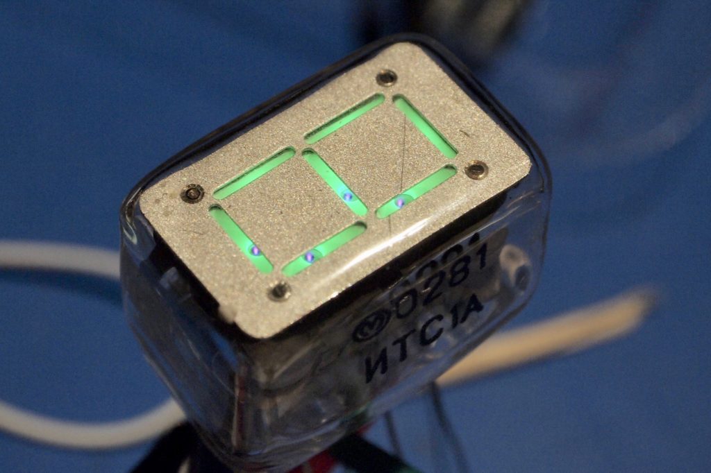
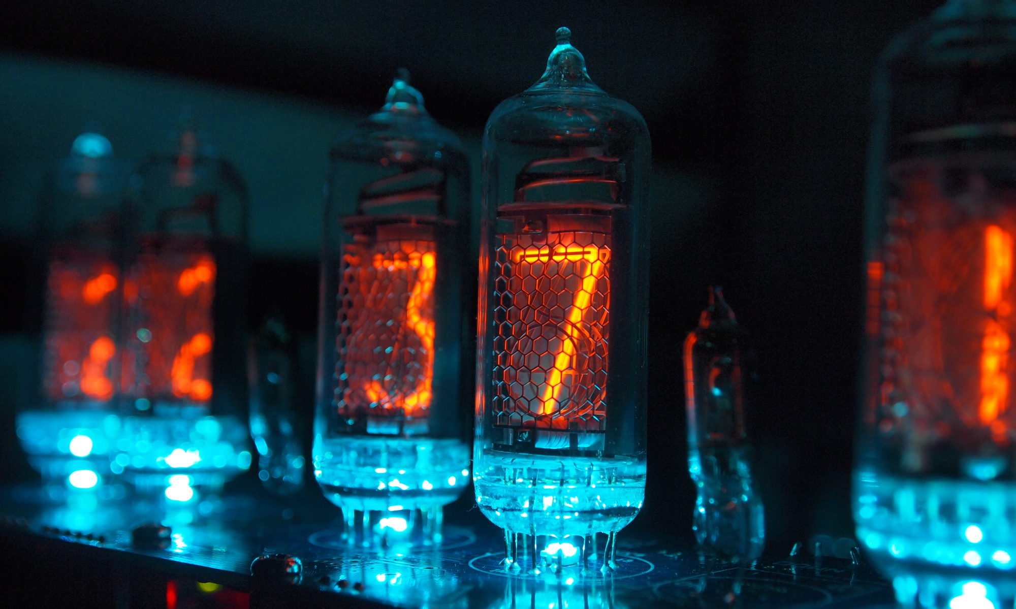
In an earlier post, I explored how to light up an ITS1A Thyratron – this is an old seven-segment display device from the former USSR:

Glowing ITS1A

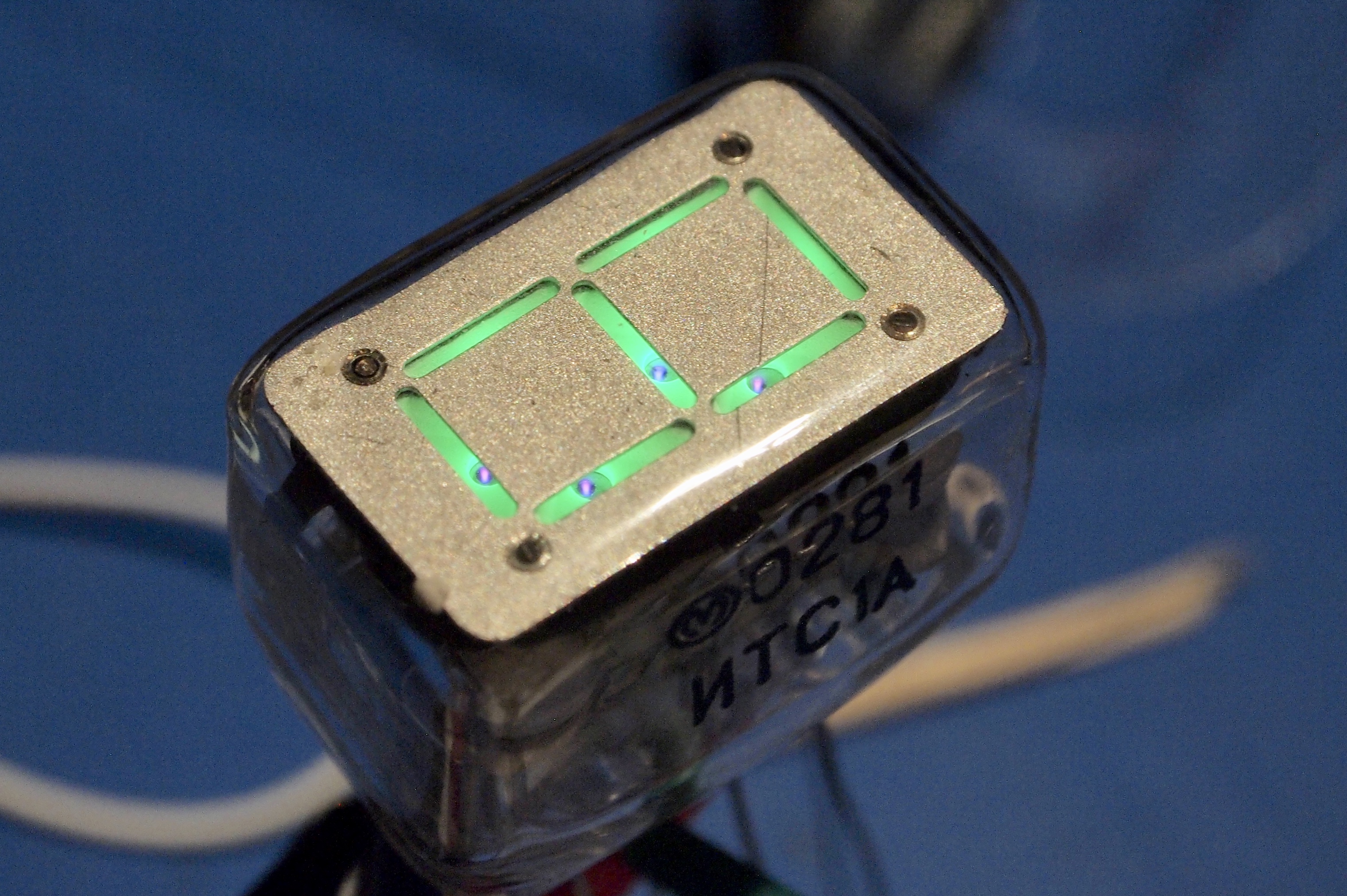
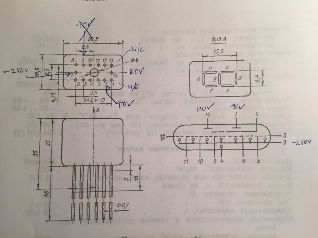
It requires some exotic voltages: -250V, +40V, +100V and logic-level signals for segment control. A high logic level can be anything between +0.4V and +4V, so a +3.3V device is perfect. The other voltages can be obtained from a 50V boost converter driven with a +5V input. I used Cockroft-Walton ladders to get +100V and -250V and a voltage divider to get the 40V. These are the pins on the tube:

Physical pin descriptions of the ITS1A

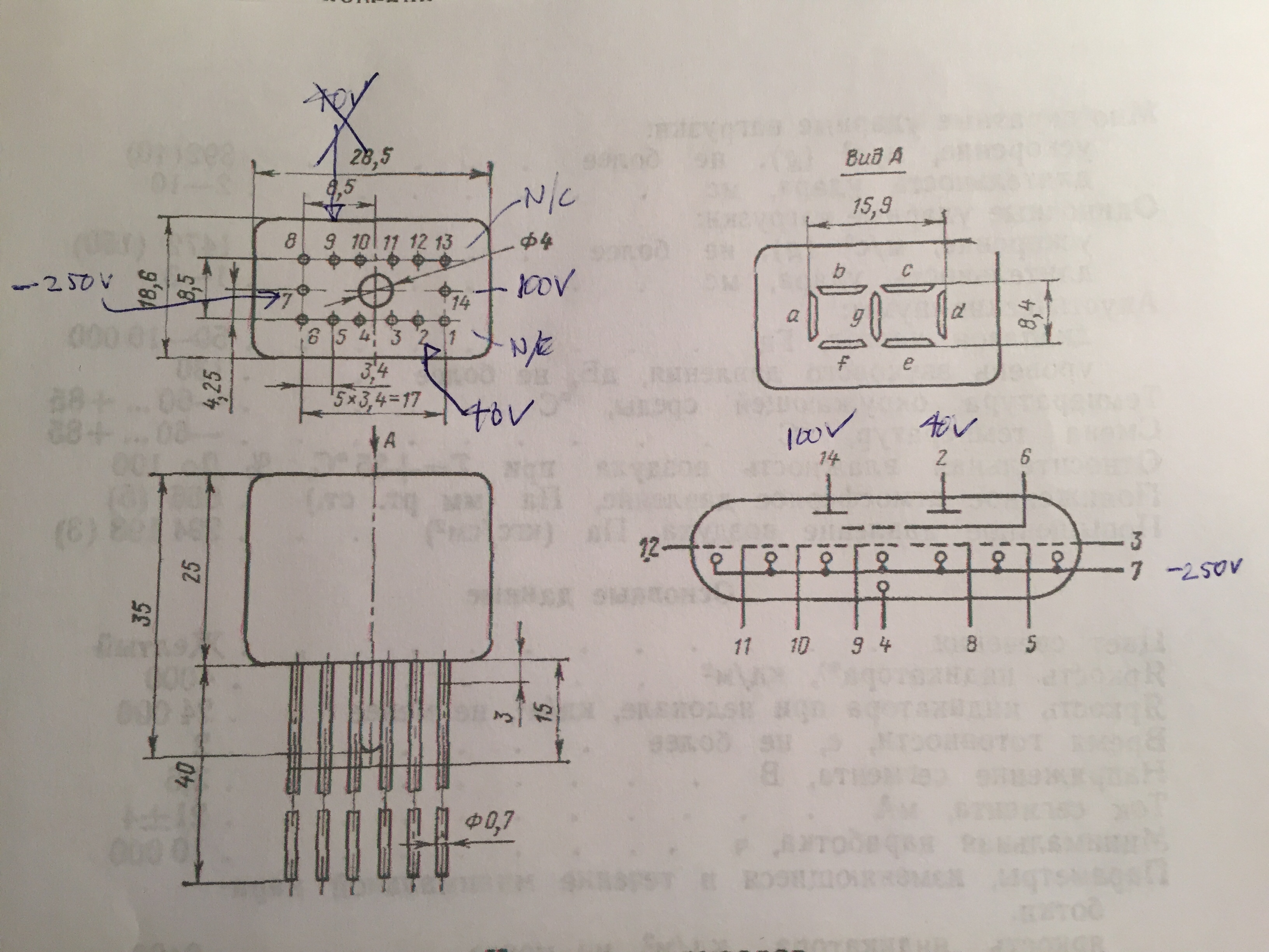
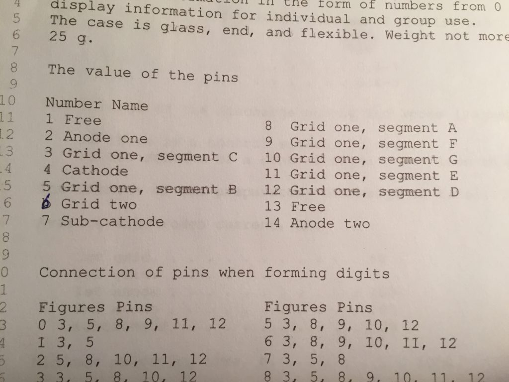
This is a description of the pins:

ITS1A pin descriptions

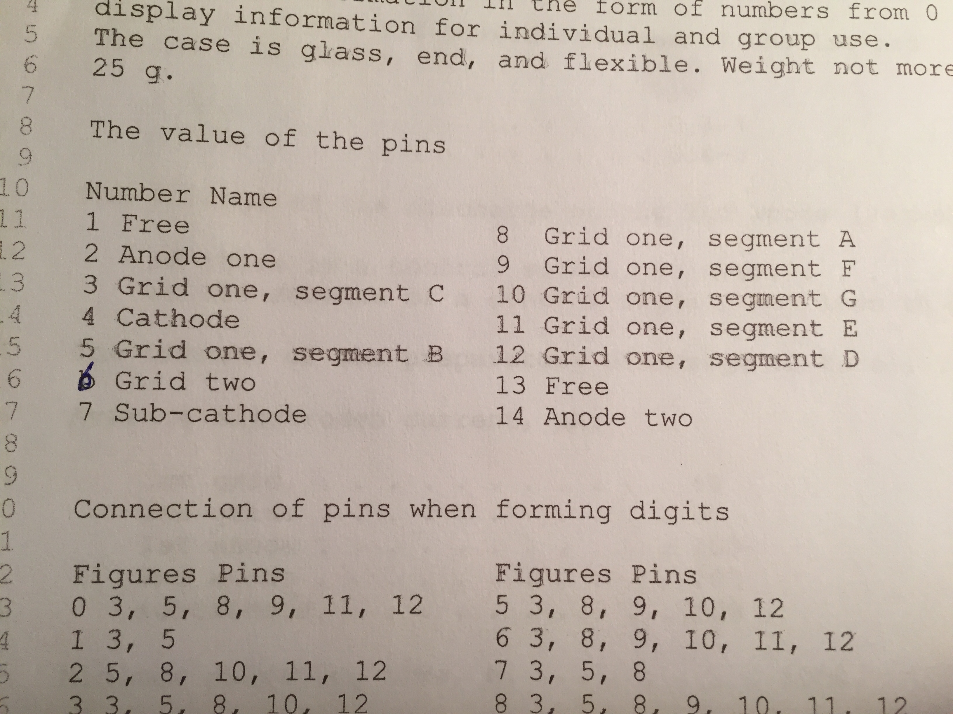
What I didn’t manage to do at the time was figure out how to select which segments get displayed. In my tests, they all lit up. Basically, if the segments are pulled to zero volts, they will be on. If the are raised above +0.4V, they will be off. But only if the other pins are held at the right voltages in the right sequence. Later on I found that I could set the segment voltages, then pull anode one and anode two low for a short period, then high again, then the displayed segments would latch on according to their voltages at the time the anodes were pulled low. The segments will stay that way, regardless of what is done to them, until the anodes are briefly pulled low again.

I suspected that grid two also played a role here, but I was unable to figure it out. Then I came across this archive, which had a circuit diagram and some PIC assembler. In that circuit, the +40V is obtained with a zener which is just connected to ground, with no pull up to keep the voltage at the zener voltage.

(NOTE: This paragraph has been edited from its original). The function of the second grid was revealed looking at the assembler source code. Basically, to set a display you start with the anodes at their set voltages and the second grid above 0.4 volts. Then you briefly pull the anodes to 0V. Then you set the voltages of the segments, then you briefly pull the second grid to 0V (note the line for the second grid below is incorrect, it should be inverted):

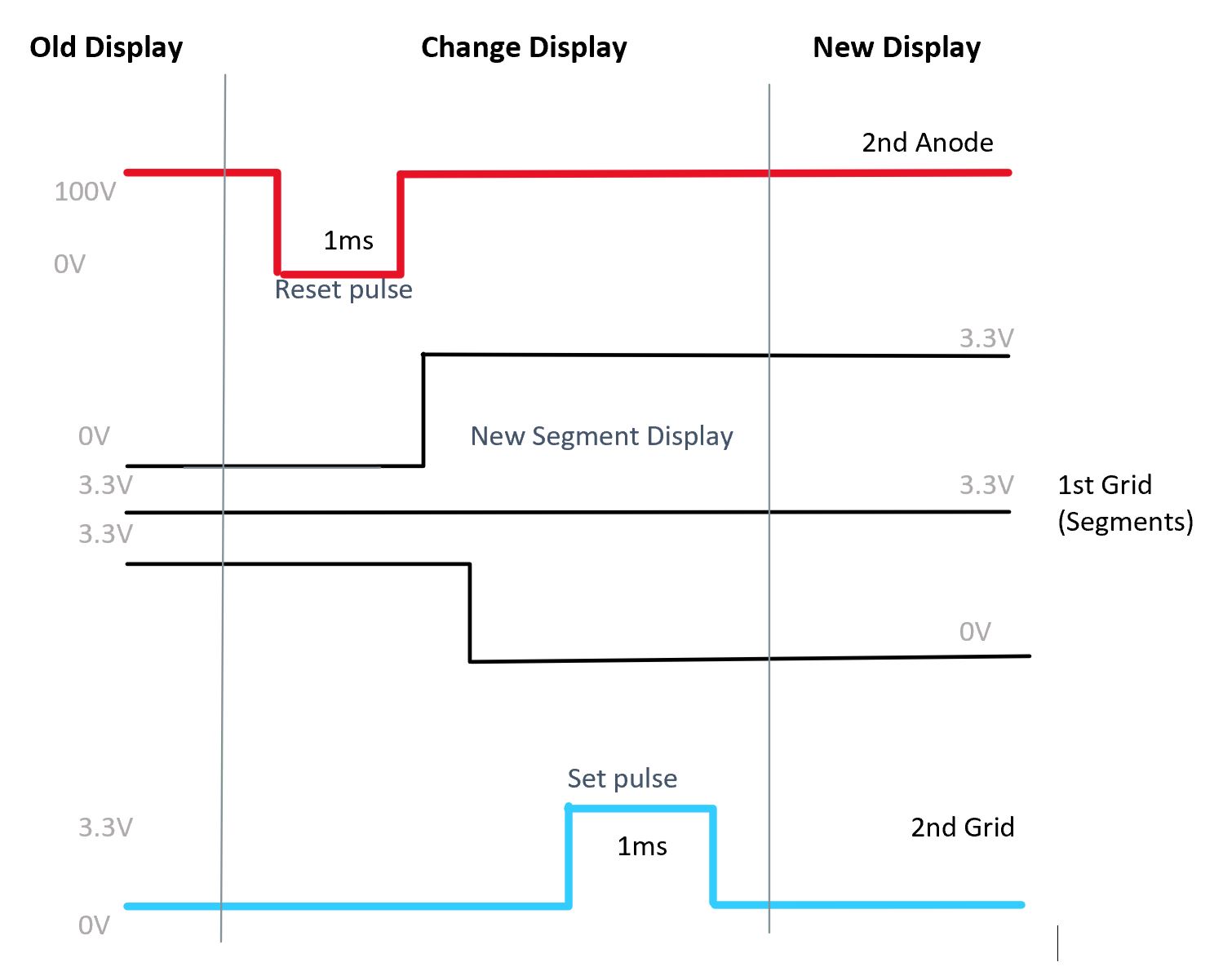
Signal sequence for setting the segments of an ITS1A

When the 2nd anode is at 100V, current also flows into the 1st anode (the 40V one) and the zener clamps the voltage to 40V. When the 2nd anode is pulled to 0V, current direction of the 1st anode is reversed, and so it is pulled to 0V too. This is what the datasheet says:

The current of the grids and the 1st anode in the non-conducting state has a positive direction, in the conducting state the direction of the current is changed.

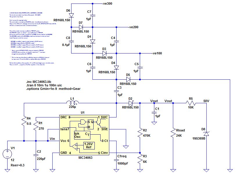
So here is a circuit diagram:

Multiplexed operation of two ITS1A tubes

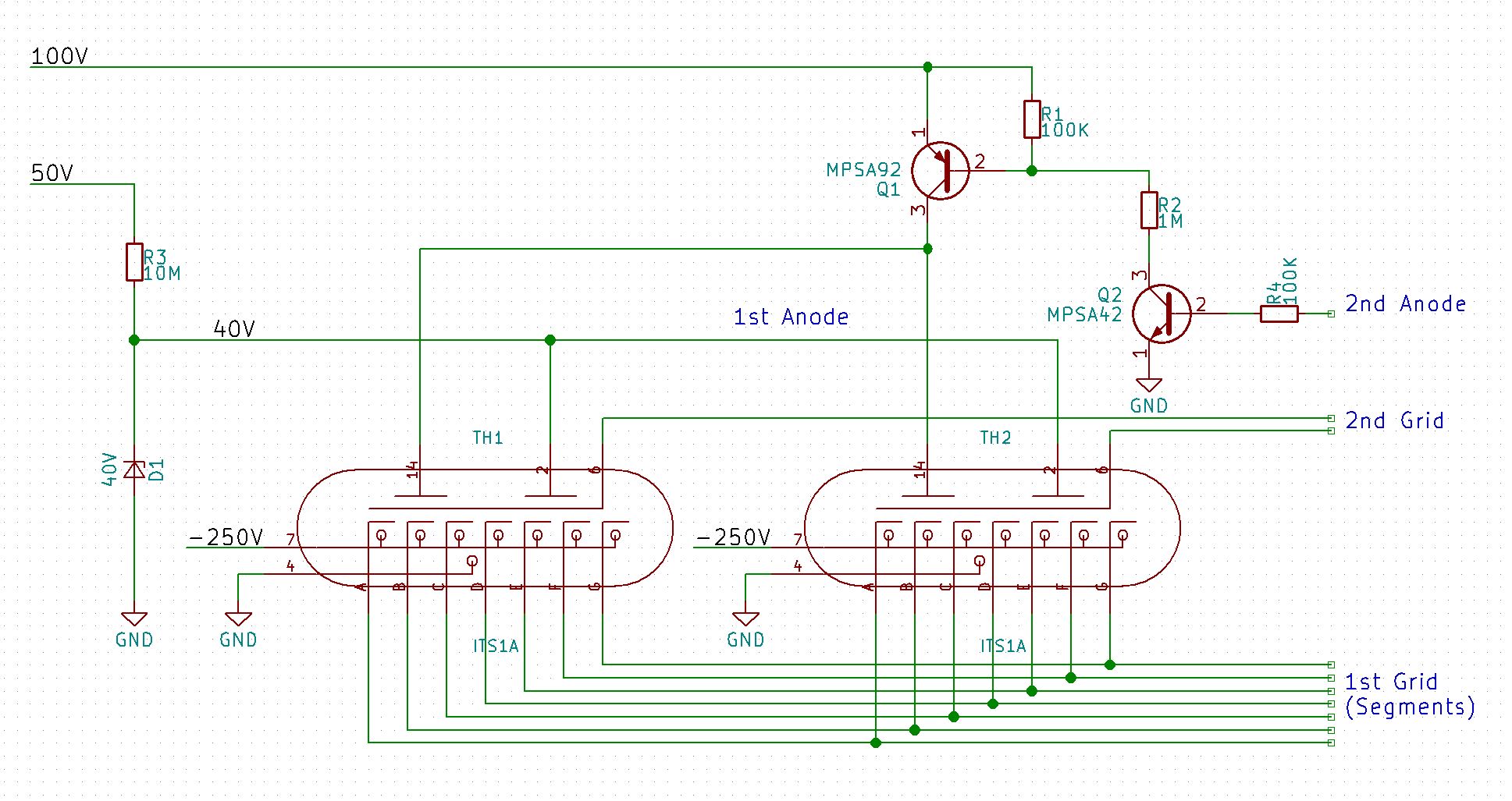
The tubes are multiplexed by setting the value of the 2nd grid individually for each tube. If the second grid on a specific tube is not pulled above +0.4V, it’s display won’t change. Note that the reset pulse only has to happen once, then you can set the display of all the tubes, one at a time by setting the segment voltages and toggling the 2nd grid on the tube(s) you want to change. Repeat the sequence the next time the display changes.

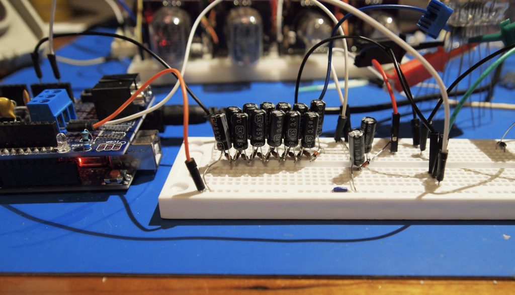
At first I was slightly annoyed that I had ITS1A tubes, which have a maximum logic level of +4.0V, v. The ITS1B tube has a maximum logic level of +5V. But it is actually a good match for modern controllers, with a +3.3V logic level. I used the trusty Wemos D1 mini Pro to test out the circuit above.

ITS1A Power Supply Part II

As I delved more into making a power supply for the ITS1A thyratron, the design became more complex. For example, to produce 100V from the inductor I would need an external FET. To switch the FET properly, I would need another transistor. If I was going to do that, I would use a completely different chip in the first place. So I re-considered what I was trying to achieve, which was simply to light up one of my tubes, just to prove that I could. So I used an existing 50V power supply I had built using the MC34063, and just built two Cockcroft -Walton ladders – a regular voltage doubler for the +100V, and a ridiculous ladder with 12 diodes for the -300V. Actually the data sheet (which I translated with the help of an online OCR and google translate) says that should be -250V. So that is what I used. Here is a picture:

A 6x voltage multiplier

I verified all the voltages, then the next step was to figure out what pins did what. Careful examination of the tube showed that two pins were cut short – this correlated with two pins described as ‘free’ on the data sheet and that allowed me to figure out what went where:

Physical pin descriptions of the ITS1A
Translated description of what the pins are

So with this I was able to wire the tube up and get it to glow:

Glowing ITS1A

You can clearly see the detail of how the phosphor is activated.

What I haven’t been able to do is to control which segments are on an which are off! It is clearly something to do with grid two, but I haven’t been able to figure it out yet.

ITS1A Power Supply

I have been meaning to get some ITS1A thyratron display tubes for some time, and finally bought some a few weeks ago. These are a seven segment display tube that looks a little like a VFD tube when on – they use the same phosphor – but they are driven entirely differently.

An ITS1A on ebay

Although they can be controlled with logic-level signals (roughly 1V to 5V), they require a bizarre set of voltages to actually activate them. The data sheet specifies around 40V, 100V and -240V. Others have apparently driven them with 50V, 100V and -300V. Yes, that’s right, that is minus 300V.

Now I don’t happen to have a power supply lying around that can produce that range of voltages, but it is surprisingly easy to build one. Or at least design one. I haven’t built it yet. The principle is to first build a simple boost converter, then use  a Cockcroft-Walton voltage multiplier driven from the un-rectified output of the inductor, to get the negative voltage. I simulated one in LTSpice. I set the output voltage to 100V. Built a diode/capacitor ladder for the -300V and used a 50V zener diode voltage clamp to create the 50V. This is what it looks like:

A boost converter that will produce the voltages needed to drive an ITS1A

This is what the simulation looks like:

Voltage plots for the boost converter

The part numbers for the diodes are just examples. I haven’t actually chosen them yet. Both the diodes and the capacitors in the ladder need to be able to handle over 100V. The capacitors should be low ESR types. The inductor needs to be able to handle the expected current, though I haven;t figured out what that is yet. However my aim with this is to just be able to test that the tubes work, and maybe have a little fun with them. An actual clock will come later.