Trials and Tribulations

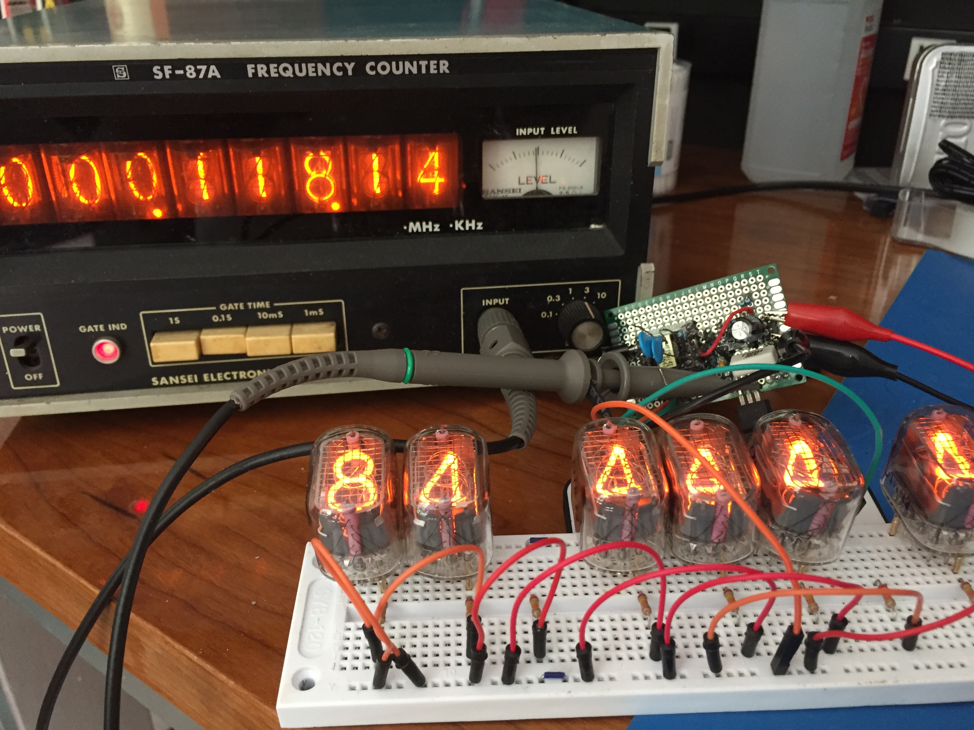
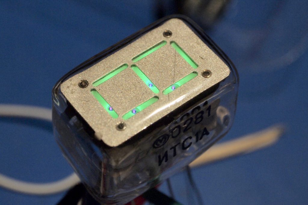
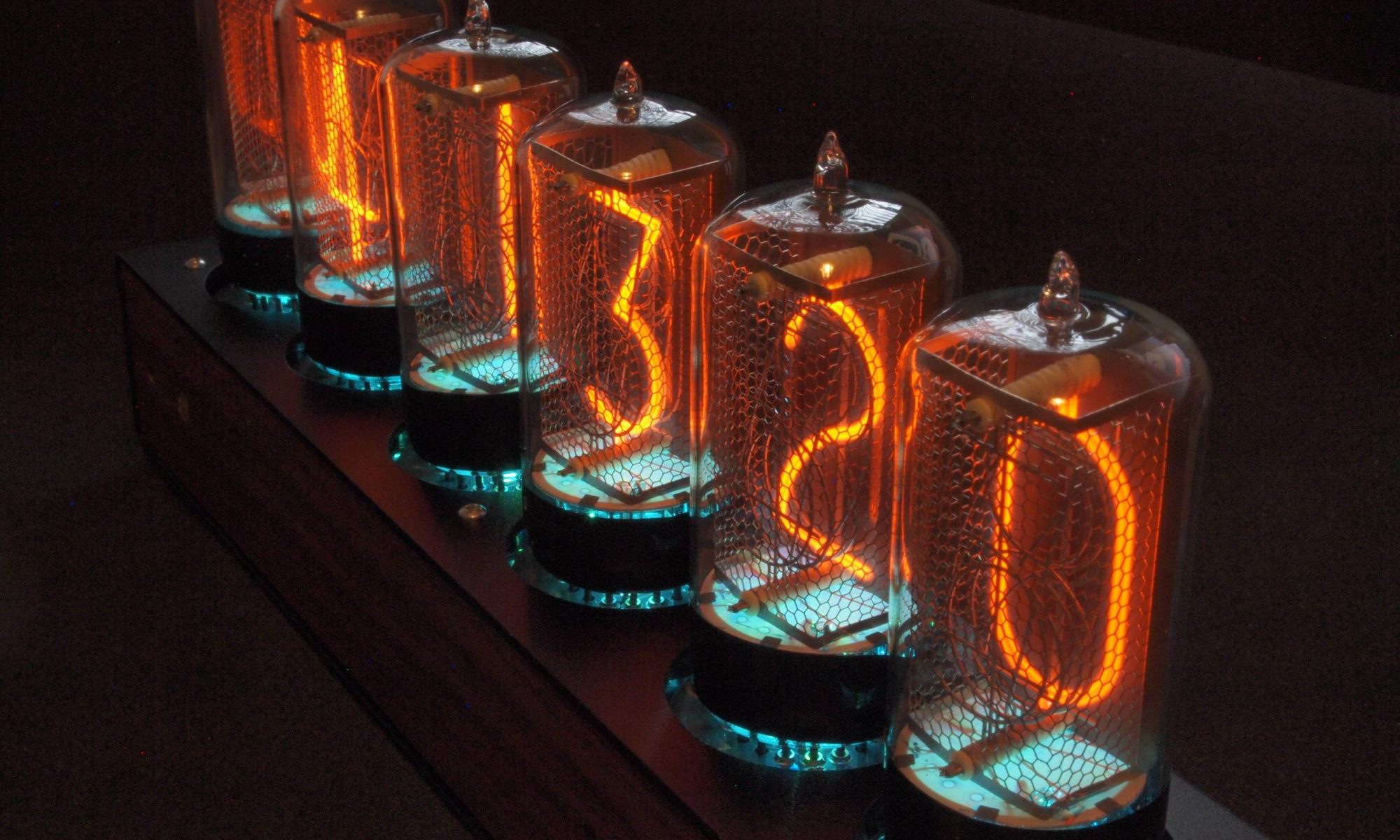
This was supposed to be a quick build of one of my one-tube-clocks, with a few tweaks to try and improve some of the features. This is what an earlier version looked like:

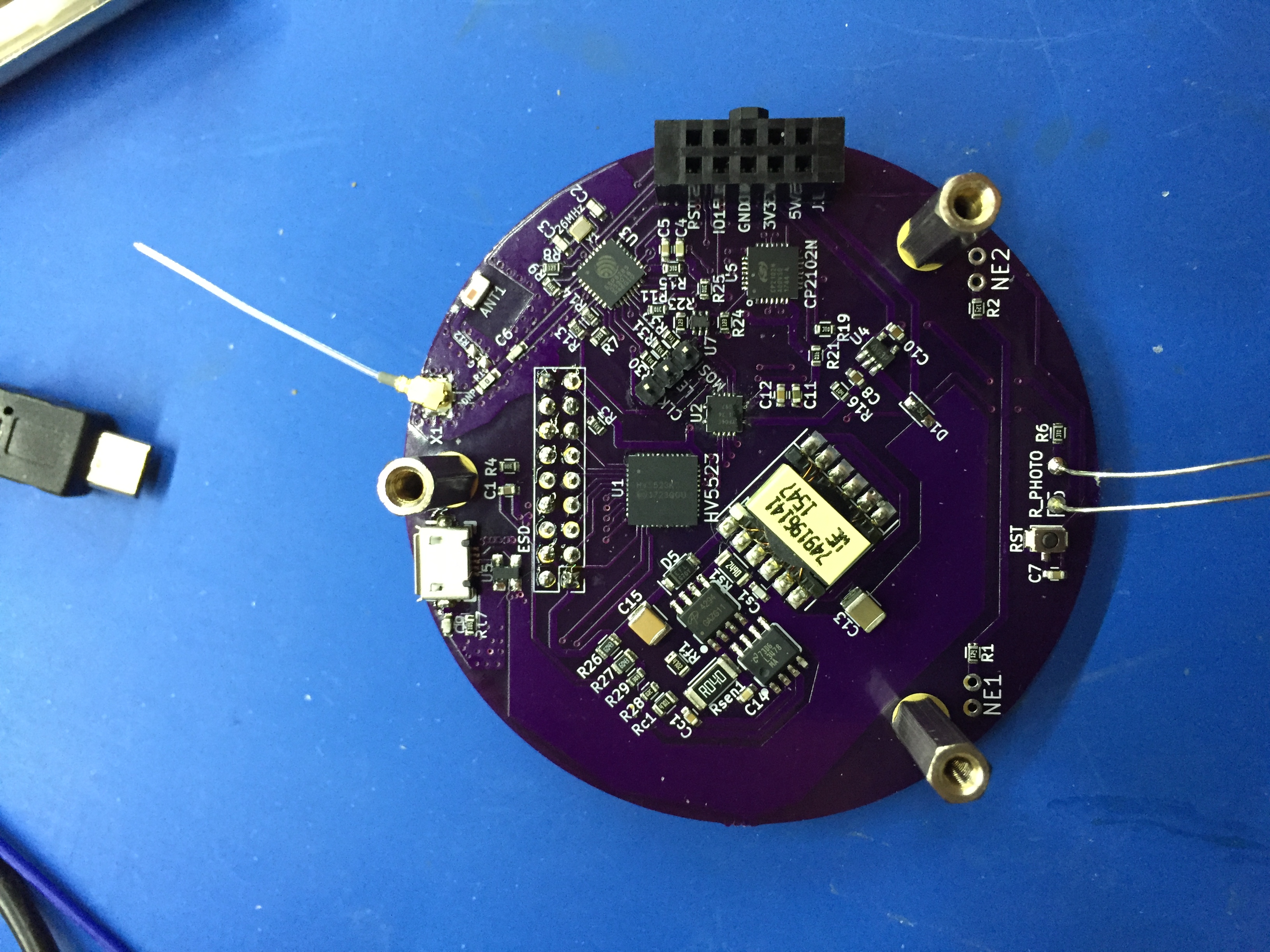
All my other builds had taken around 3 hours, and the worst that went wrong was a few dry joints. This build was very different:

  1. I had three attempts at getting the solder paste applied – that is three complete wipes and restarts.  It kept smudging, or leaking onto adjacent pads. This was an omen.
  2. Finally I had something I could work with, but I had to touch up some teeny tiny pads on the CP2102N footprint – a QFN28. They were right next to a trace I had cut. I got solder-paste in the cut. I had to get it out, otherwise it would short the two halves of the trace back together. Cue some very fiddly cleaning using a magnifier.
  3. Finally got everything in place, and transferred the board to my hotplate. It was almost cooked and I realized I had forgotten a component, so I had to take it off and let it cool and then add the missing component.
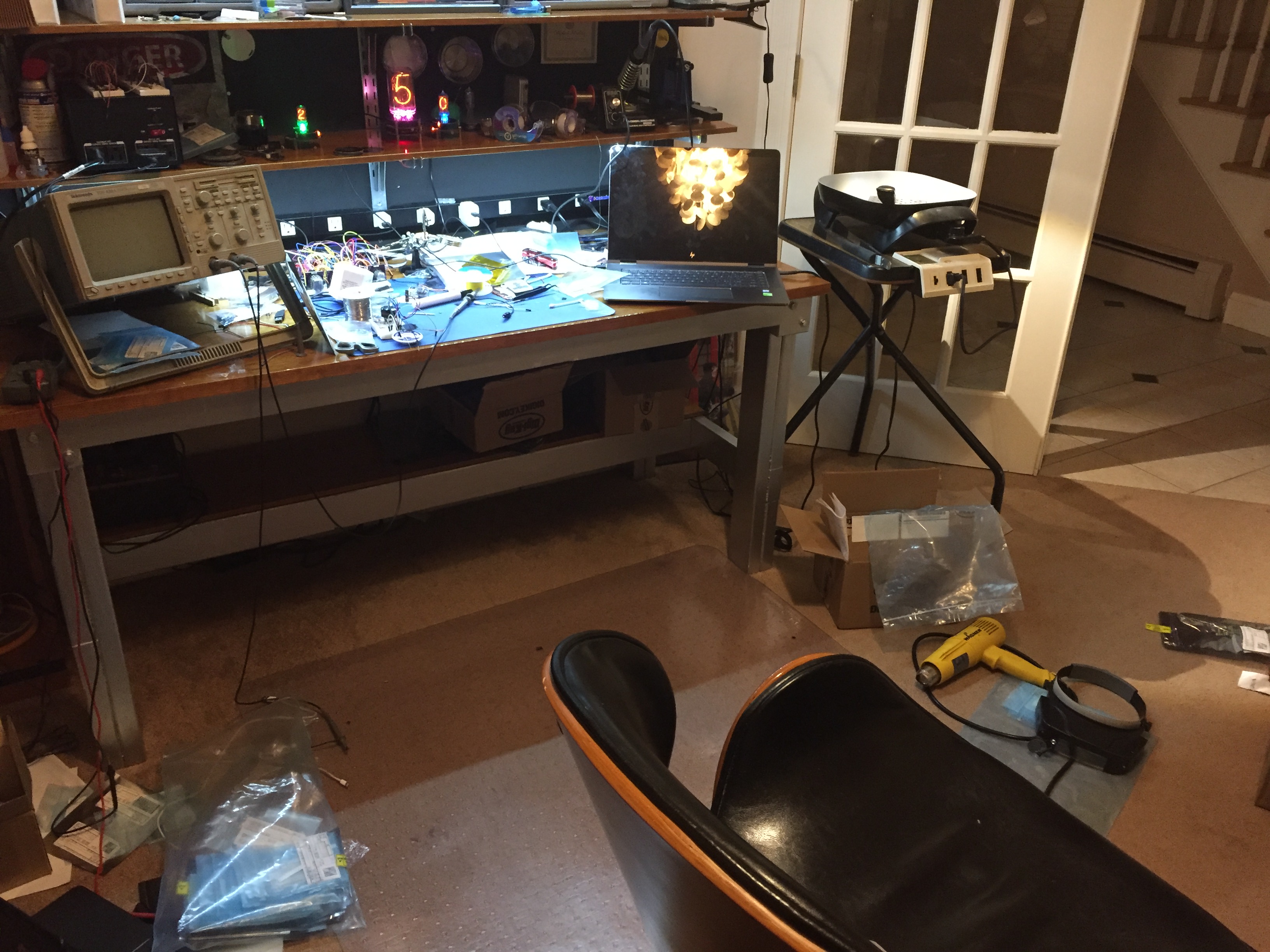
  4. When transferring the board back to the hotplate, I spilled the whole lot on the floor! Fortunately most stayed put, but I had to spend quite a bit of time inspecting things to make sure it was OK, moving some items back into place, and replacing others that had vanished into the carpet.
  5. Second cooking. Looking good.
  6. First test: Plug it into a USB port on my computer. No beeping sound. Nada. I check voltages on the board in a few places, they are all fine, what is going on? I decide to try another device in the same USB port. Nothing. Now this is worrying: had I blown the port? Then I remembered I had the laptop connected to bluetooth audio. The receiver was switched off. So I disconnected bluetooth and plugged my second device into the USB port to check the port, nice noise, port was fine. Now I’m thinking that my new board is probably fine too. Plug that in, no noise. Nada. So, check the soldering. Looks fine, but I touch up the pins on the USB/UART chip that handle the USB connections and now I get the happy sounds from the laptop, so I solder on some indicator LEDs and some connectors.
  7. Next test: Program the ESP8285 on the board. No go. Laptop can’t talk to the ESP8285. I spent quite a while trying to trouble-shoot this. I touched up the pins on the USB/UART chip that interface to the ESP8285. No difference. I wondered if maybe the second cooking had broken the ESP. It looked like there was a blister on it. However I figured I should check some of the signals on the ESP, so I start counting clockwise from pin 1. When I got to the pin that should have been GPIO0, something didn’t seem right. It shouldn’t have been on that side of the board. Then I realized: I had soldered the chip on the wrong way! Arghhhhhh. I was resigned to just salvaging what components I could on the board and throwing it away, but I was tempted to heat the board back up again, pull the ESP and solder a new one on. To do that I would have to unsolder those connectors and LEDs. Not a trivial task. Then it occurred to me: I have a heat gun (not one specific to PCB work, just a regular old heatgun like you might use for stripping paint). I figured I might as well see if I could use it to de-solder the ESP, and amazingly it worked. I fitted a new chip in the right orientation and used the heat gun to solder it. I tried to program it again, and it worked! I can connect to my web server running on the ESP and mess with the controls.
  8. So I plug in a Nixie tube adapter and nothing. Oh come on! I start checking voltages and there is no 5V. 5V is used for two things on this board: Lighting up the LEDs and driving the HV switch. I quickly narrow it down to a dry joint on a diode from the USB power line to my 5V circuit.
  9. OK. Plug in the nixie adapter again and it lights up. We are in business! Wait, though. The LEDs on the adapter aren’t lighting up. This is getting ridiculous (maybe that should be more ridiculous). These aren’t just regular LEDs, they are NeoPixels. I just checked the power above, so I look at the signal lines. They go through a 3V3 to 5V level converter. The signal was non-existant. It was 0V on the 3V3 side and weirdly it was 5V on the 5V side. This is not an inverting level converter, so it should have been 0V too. Except it shouldn’t be 0V at all, it should have a PWM signal on it. I check the connections from the ESP to the level converter, it is all good. There is a pull-up resistor in that line, so something was driving it to zero. All the signals to the HV chip go through the same level converter, and they were working just fine. Finally, though, I decide it has to be the level converter, because 0V should not become 5V. Time to de-solder that chip (another QFN-type package) and replace it.
  10. Plug in the Nixie adapter again, and now I have LEDs. But now the Nixie tube is blank! It has to be the level converter again, so I start tracing signals and yes, I have a dry(ish) joint on one of the pins. I touch that up, plug in the adapter and, finally, everything works.

So, eight hours later and I’m actually quite please that I managed to trouble-shoot this. Plus I learned how to do re-work using a hot air gun (BTW, the gun does have various temperature and ‘ferocity’ settings).

I have yet to clean up though:


Display the Time on an Old Frequency Counter

A while back I bought an old frequency counter that has a Nixie tube display. It is a Japanese SF-87A made by the Sansei Electronics company. I bought it for the tubes – eight CD66 – however, when it arrived, it was in very good condition and worked just fine, so I decided not to harvest the tubes from it. I subsequently used it to display the frequency of my Nixie power supply, but that was just looking for an excuse, I didn’t actually need to use it for that:

Displaying the frequency of my Nixie power supply.

This left me in a bit of a quandry, but not too long ago Alic Loeliger suggested on the Nixie Clocks Fan Page on Facebook that I could get it to display the time by just sending the right number of pulses to it in a given time. This was such a simple idea that I had to try it.

The maximum gate time of the counter is 1 sec, and the largest number I would need to display would be 125959 (aka 12:59:59) for a 12-hour clock, or 235959 (aka 23:59:59) for a 24-hour clock. In other words, I would need to generate (at most) either a 126KHz signal, or a 236KHz signal. As I was doing this in software, because I am a software engineer, I went for the lower of the two numbers – I wanted to make sure that one of the processors I had available would be able to do it. I had a choice of an Arduino Uno, or an ESP8266. I ended up going with the ESP8266, which I programmed using the Arduino ESP8266 toolset.

At first, I split the number of pulses evenly over the gate time. i.e. if I needed to display 10:00:00, I would send send one pulse every 0.00001s. Then I realized that the counter just counted the number of pulses that occurred within the gate time, then divided that count by the gate time to get the frequency.  In other words, all I had to do was generate the right number of pulses in less than one second. However, when I tried this, it didn’t work – I assume the pulses were too close together for the counter to detect them. So, back to sending them spread over the gate period.

The result is kind of, sort of OK. The higher the frequency gets, the less able it is to accurately display the seconds – there is some ’rounding’ involved. Here is a video of it displaying 03:07:21 – note I have no control over the placement of the thousand separators:

Here is the source code:

#include "Arduino.h"
#include 

// Use pin 0
#define PIN 0

volatile unsigned long scaledPeriod = 0;
unsigned long oldMicros = 0;
unsigned long counter = 0;

/*
 * generate the pulse train in a timer interrupt. The function uses
 * the period, rather than the frequency. This is in 1/100,000,000s
 * units
 */
const int counterPeriod = ESP.getCpuFreqMHz() * 10;

void ICACHE_RAM_ATTR isr() {
    uint32_t ccount;
    __asm__ __volatile__("esync; rsr %0,ccount":"=a" (ccount));
	timer0_write(ccount + counterPeriod);

	unsigned long newMicros = micros();
	// micros is millionths of a second. Our period is in 
	// 100,000,000 of a second, so we multiply the difference
	// by 100
	unsigned long diff = (newMicros - oldMicros) * 100;
	if (scaledPeriod > 0 && (diff > scaledPeriod)) {
		digitalWrite(PIN, HIGH);
		oldMicros = micros();
	} else {
		digitalWrite(PIN, LOW);
	}
}

void setup()
{
	// Set to some arbitrary time
	setTime(3, 7, 20, 1, 2, 2018);
	pinMode(PIN, OUTPUT);
	timer0_isr_init();
	timer0_attachInterrupt(isr);

	timer0_write(ESP.getCycleCount() + counterPeriod);
}

unsigned long  oldTime = 0;

void loop()
{
	unsigned long newTime = hour() * 10000 + minute() * 100 + second();

	if (newTime != oldTime) {
		oldTime = newTime;
		if (newTime != 0) {
			// Need a numerator that is >> newTime could be
			scaledPeriod = 100000000/newTime;
		} else {
			scaledPeriod = 0;
		}
	}
}

This code has some problems! As newTime gets larger, scaledPeriod loses more and more precision. Furthermore, because the interrupt routine is called at a fixed periodicity, it is essentially sampling the waveform. Both of these things mean that the displayed time gets less accurate as the absolute size of the number being displayed is increased.

In retrospect, it would be better to adjust the periodicity of the interrupt routine to match that of the waveform we are trying to generate. That would be an improvement, but we would still have problems caused by the rather coarse granularity of the timer we have available.

Still, the result isn’t too bad.

ITS1A Power Supply Part II

As I delved more into making a power supply for the ITS1A thyratron, the design became more complex. For example, to produce 100V from the inductor I would need an external FET. To switch the FET properly, I would need another transistor. If I was going to do that, I would use a completely different chip in the first place. So I re-considered what I was trying to achieve, which was simply to light up one of my tubes, just to prove that I could. So I used an existing 50V power supply I had built using the MC34063, and just built two Cockcroft -Walton ladders – a regular voltage doubler for the +100V, and a ridiculous ladder with 12 diodes for the -300V. Actually the data sheet (which I translated with the help of an online OCR and google translate) says that should be -250V. So that is what I used. Here is a picture:

A 6x voltage multiplier

I verified all the voltages, then the next step was to figure out what pins did what. Careful examination of the tube showed that two pins were cut short – this correlated with two pins described as ‘free’ on the data sheet and that allowed me to figure out what went where:

Physical pin descriptions of the ITS1A
Translated description of what the pins are

So with this I was able to wire the tube up and get it to glow:

Glowing ITS1A

You can clearly see the detail of how the phosphor is activated.

What I haven’t been able to do is to control which segments are on an which are off! It is clearly something to do with grid two, but I haven’t been able to figure it out yet.

ITS1A Power Supply

I have been meaning to get some ITS1A thyratron display tubes for some time, and finally bought some a few weeks ago. These are a seven segment display tube that looks a little like a VFD tube when on – they use the same phosphor – but they are driven entirely differently.

An ITS1A on ebay

Although they can be controlled with logic-level signals (roughly 1V to 5V), they require a bizarre set of voltages to actually activate them. The data sheet specifies around 40V, 100V and -240V. Others have apparently driven them with 50V, 100V and -300V. Yes, that’s right, that is minus 300V.

Now I don’t happen to have a power supply lying around that can produce that range of voltages, but it is surprisingly easy to build one. Or at least design one. I haven’t built it yet. The principle is to first build a simple boost converter, then use  a Cockcroft-Walton voltage multiplier driven from the un-rectified output of the inductor, to get the negative voltage. I simulated one in LTSpice. I set the output voltage to 100V. Built a diode/capacitor ladder for the -300V and used a 50V zener diode voltage clamp to create the 50V. This is what it looks like:

A boost converter that will produce the voltages needed to drive an ITS1A

This is what the simulation looks like:

Voltage plots for the boost converter

The part numbers for the diodes are just examples. I haven’t actually chosen them yet. Both the diodes and the capacitors in the ladder need to be able to handle over 100V. The capacitors should be low ESR types. The inductor needs to be able to handle the expected current, though I haven;t figured out what that is yet. However my aim with this is to just be able to test that the tubes work, and maybe have a little fun with them. An actual clock will come later.