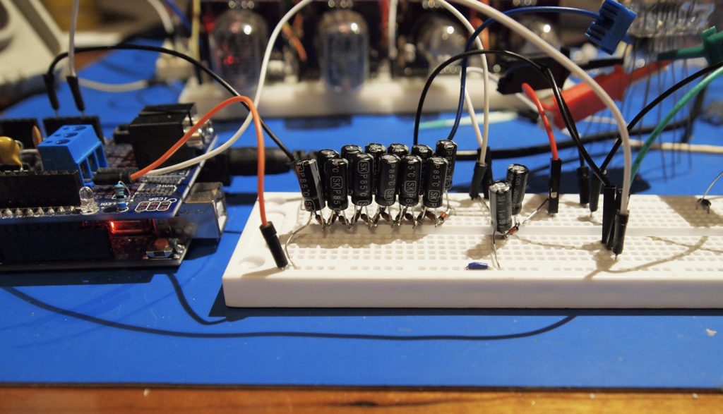
As I delved more into making a power supply for the ITS1A thyratron, the design became more complex. For example, to produce 100V from the inductor I would need an external FET. To switch the FET properly, I would need another transistor. If I was going to do that, I would use a completely different chip in the first place. So I re-considered what I was trying to achieve, which was simply to light up one of my tubes, just to prove that I could. So I used an existing 50V power supply I had built using the MC34063, and just built two Cockcroft -Walton ladders – a regular voltage doubler for the +100V, and a ridiculous ladder with 12 diodes for the -300V. Actually the data sheet (which I translated with the help of an online OCR and google translate) says that should be -250V. So that is what I used. Here is a picture:
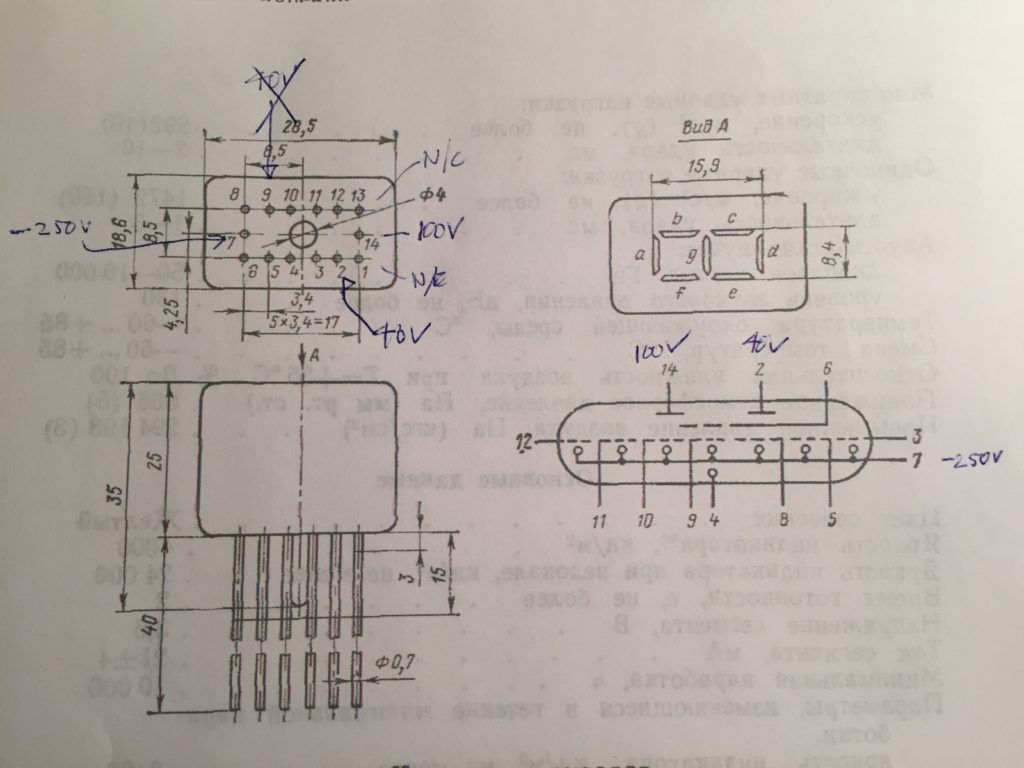
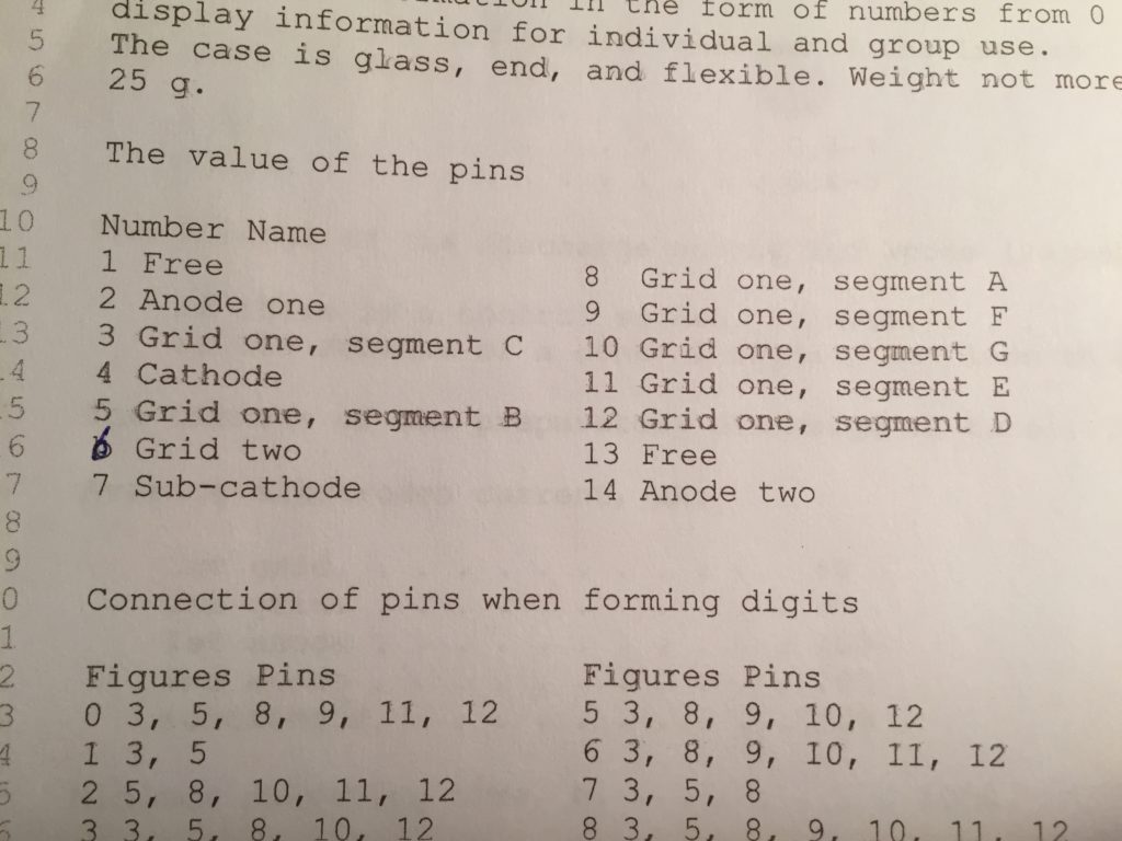
I verified all the voltages, then the next step was to figure out what pins did what. Careful examination of the tube showed that two pins were cut short – this correlated with two pins described as ‘free’ on the data sheet and that allowed me to figure out what went where:
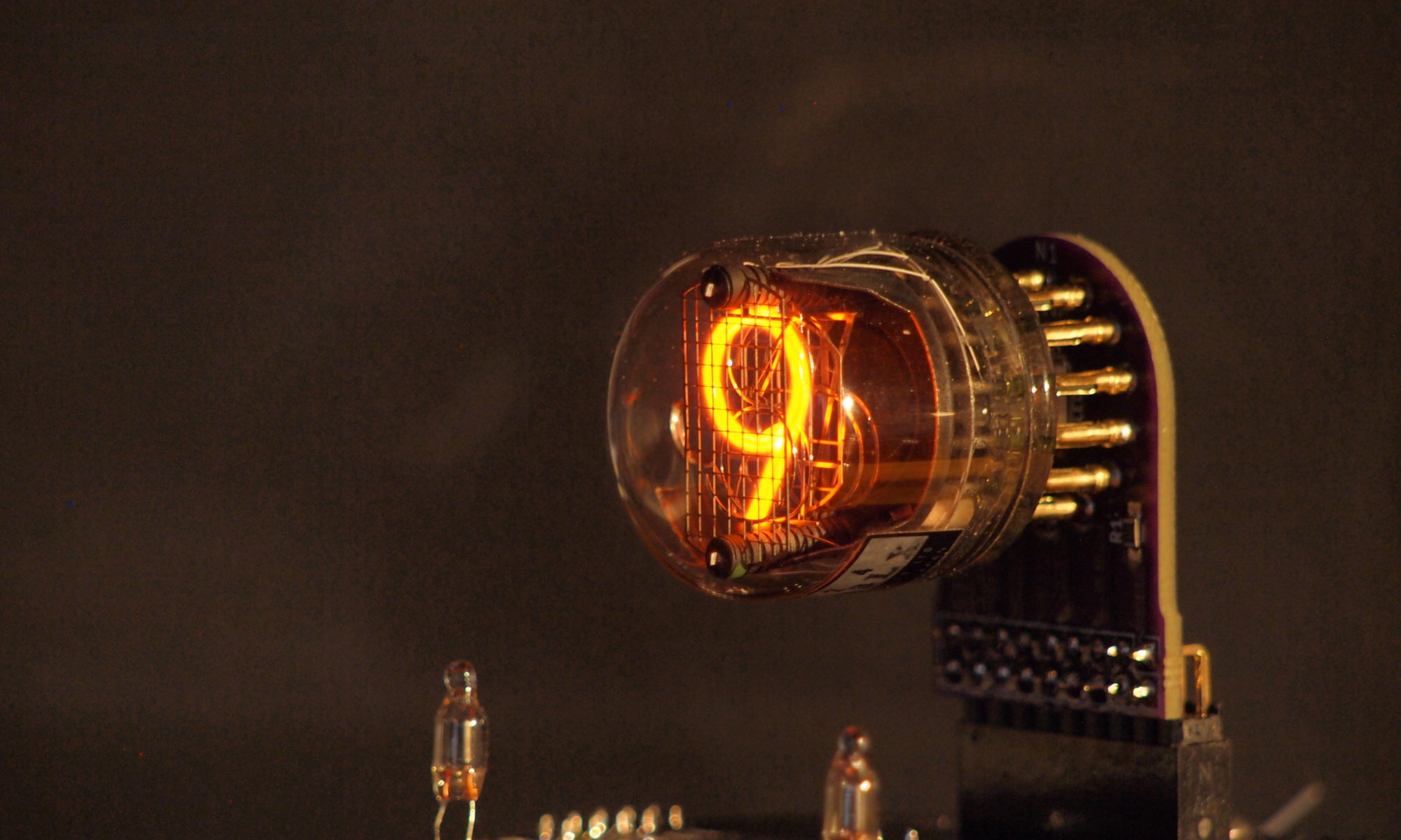
So with this I was able to wire the tube up and get it to glow:
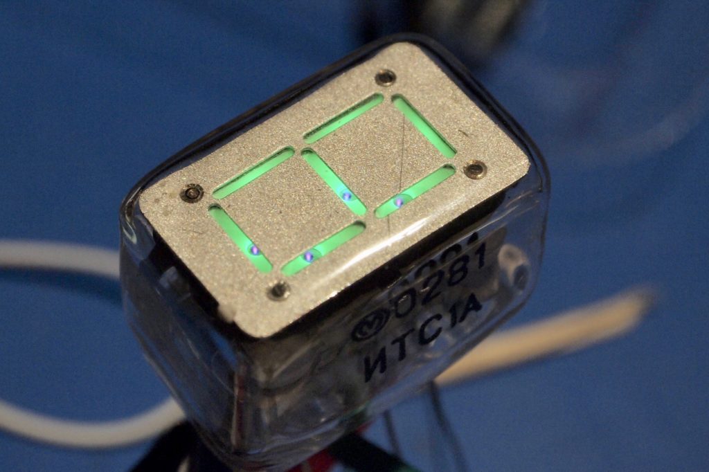
You can clearly see the detail of how the phosphor is activated.
What I haven’t been able to do is to control which segments are on an which are off! It is clearly something to do with grid two, but I haven’t been able to figure it out yet.
Excellent job, Paul. An interesting project.
I hope to see more of this project in the future.