About 7 months ago, I watched a video by glasslinger about adding a nixie tube display to a vintage radio. This was something I had wanted to do for a while, but I didn’t know how to read the tuned frequency from the radio. There were many interesting parts to the video (I recommend you watch it), but one of the things I learned was that vacuum tube radios that had tranformers, actually generated voltages with those transformers that were high enough to drive Nixies.
I spent a little while trying to find a radio with an input transformer like that, and in the meantime, I started researching vacuum tube power-supply design. That was when I finally realized that these things were still being made for guitar (and HiFi, but especially guitar) amplifiers. So you could actually buy new transformers and new vacuum tubes and new chokes that you could use in a new power supply. That is when I got really serious about this.
At this point, two sites influenced my initial design. The first was ‘Fun With Tubes’, which had several simple designs. The second was ‘DIY Audio Projects’. which went in to much greater depth about tube selection and circuit calculations. In particular, the latter had a nice chart showing the voltage drop that different vacuum rectifier tubes had. Some of them were quite startling – for example the 5Y3, used by the first site, had a voltage drop of almost 45 volts for a plate current of 100mA, compared with only 15V for the 6CA4. What’s more, the 6CA4 is still in production.
The DIY Audio projects site showed a long series of manual calculations to determine properties of that simple un-regulated power supply. I entered these in a spreadsheet to make life easier, however, I later found a little application called psud2 (power supply designer 2) that did the same thing using a simulator and a few values from the data sheets. The important thing being that the maximum 6CA4 plate current (which is on a cold start) does not exceed the maximum allowed plate current on the data sheet.
Taking a hint from the DIY Audio Projects page, I decided to go with a one-stage choke filter to smooth the output of the rectifier tube. Confusingly (for me) everyone refers to this as the ‘input filter’. I guess because it is the input to whatever comes after this stage – usually an amplifier. So this is what I ended up with (from dsud2):
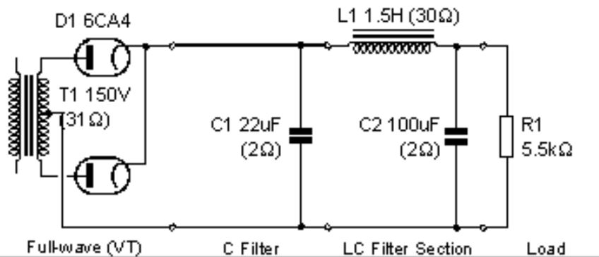
Obviously(?) this is just the output stage. On the input side is 125V 60Hz, a 1A slow blow fuse in the hot line and a neon indicator across hot and neutral, so I could tell when it was on.
Something I omitted was a resistor to drain the capacitors when power was removed. Those capacitors can hold a charge for a long time. I soon added one. Experience is wonderful thing.
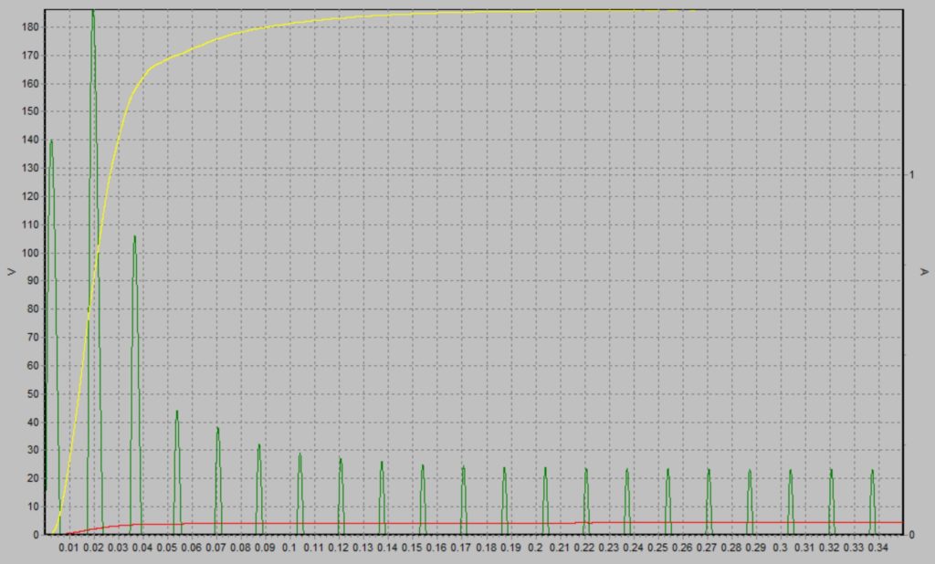
Here is a chart from psud2 showing the expected output:
The next stage was to select some actual components and bread-board it. I ended up going with a 269BX transformer from Hammond, a 156R choke (also from Hammond) and a new 6CA4 from JJ Electronics. All the rest are just suitably spec’d parts from DigiKey and a bunch of terminal strips, screws, fuses, switches, fuse holders etc. from my local electronics store.
I would show you a picture of the breadboard, but I will save that for part 2, when I discuss how to deal with the potential for voltage sag.