I’ve used the KRC-86B bluetooth module in several projects. It is tedious trying to figure out which one I am about to connect to, because they all have the same name, so it would be great to be able to rename it. It would also be nice if the name meant something.
This is a summary of this instructable. Things have changed a little since it was written, so this little post summarizes the state of play at the moment. It is still well worth watching the video in the instructable and reading the comments.
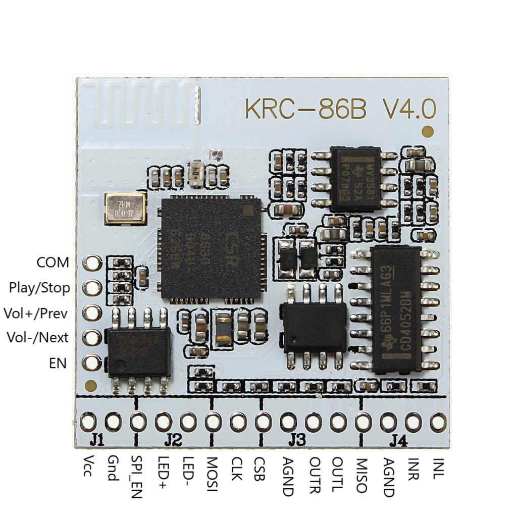
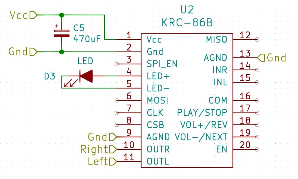
To rename the module you need to modify one of the settings stored on it. This is done using the SPI interface that is part of the module. I’ve documented the pins in the image below – on the module itself they are marked as NC.
KRC-86B bluetooth module pin assignments
So all you have to do is to send commands over SPI! This might sound a little daunting, but actually it is quite simple. The CSR8630 chip on the module was developed by Qualcomm, and they developed windows software to do the heavy lifting. The software is called BlueSuite. Qualcomm no longer provide this, but you can get multiple versions here. You should use the latest version there, which is bluesuite.win.2.6_installer_2.6.11.1937.zip.
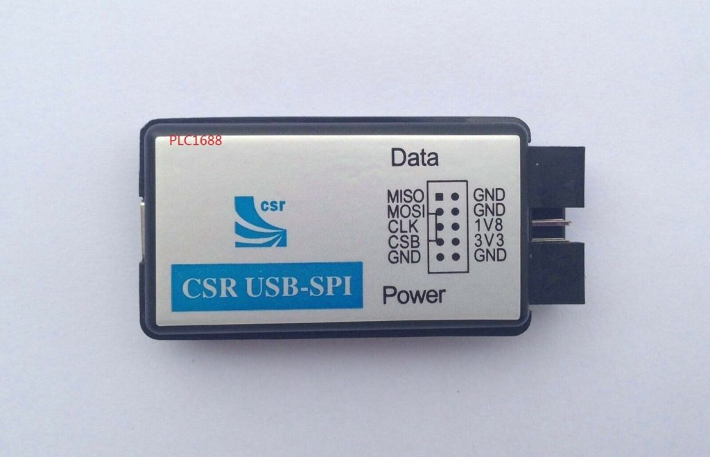
Next you will need a USB to SPI converter. I used this one:
PLC1688
You will need to figure out some way to attach this to the KRC-86B. Check the actual pinouts on whatever USB adapter you use.
Install the BlueSuite software.
Connect the 3V3 pin to Vcc on the module
Connect a 10k pullup resistor between Vcc and SPI_EN to enable the SPI interface on the module.
Connect MISO to MISO, MOSI to MOSI, CLK to CLK and CSB to CSB.
Plug the PLC1688 (or whatever) into your PC.
Run pstool (which is what is installed by the BlueSuite installer). It should detect the module and you can just hit OK. If it doesn’t detect it, troubleshoot your connections.
Make a backup of the module – File>Dump
Search for name
Change it
Check it changed to what you want using your phone
And that is it. Pretty simple.
Many thanks to sjowett. I spent years searching for this.
I’m writing this as much for my own use as anything else – I keep having to re-invent this solution every time I fix a vintage radio.
Most vintage radios are AM only, and in my part of the world, the only thing on AM is talk radio. Even if that weren’t the case, let’s be honest, most of what people listen to these days is streamed. I don’t like my radios to be shelf-queens, I want to be able to use them and honestly, the sound from the bigger radios is great.
One solution to this is to add an aux-in so that you can plug in an external source and play it through the radio. this certainly works (and you can use most of what is here to do that), but you still need a Bluetooth dongle and leads, and you have to charge it up and turn it on and switch the radio to aux-in. This solution wires the Bluetooth ‘dongle’ into the radio directly, so that it comes on when the radio comes on.
Overview
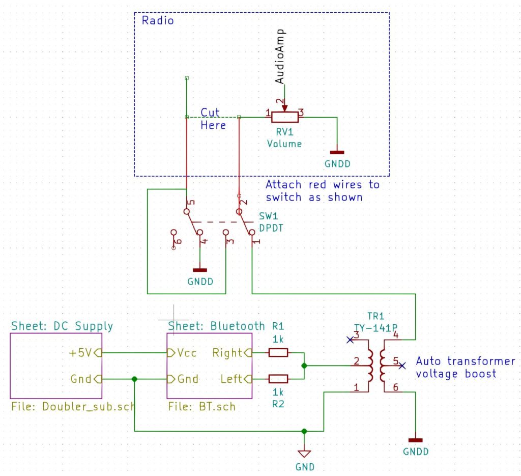
This shows a high-level view of what we are going to do:
Bluetooth Mod Overview
Radio Modifications
Let’s look at the radio block first. The modification here is the same regardless of what external source we are going to wire in. We are going to wire our new audio source across the volume control.
Find the lead going to the volume control that is not connected to ground and does not go to the audio ouput stage. we will cut this wire and route it to a double-pole double-throw switch. A double-pole double-throw switch is simply a switch with two positions (double-throw) that switches two sources at the same time (double-pole). In one position the switch will connect that wire back to the volume control. In the other position it will connect our new audio source instead.
NOTE: It is a good idea to use shielded cable to make the connections between the radio and the switch. Connect the shield to chassis ground.
In the diagram above you can see (hopefully) that when our new audio source is connected, the original one is connected to ground rather than just left floating. This helps stop sound from the RF/IF stages of the radio from bleeding through to the speaker.
Bluetooth Module
The next block to look at as the one marked Bluetooth. You will see that the right and left channels are connected together via two 1k resistors. The use of these resistors prevents the output from one channel destroying the other channel.
Transformer
The next block we will talk about is the auto-transformer. This can serve two purposes.
The first is to boost the output of the Bluetooth module so that it has about the same loudness for a given volume setting as the radio itself. The particular model I am using is the TY-141P. If it is wired as shown in the diagram it gives a 1:2 voltage boost, which seems about right on all the radios I have modded. Triad make another transformer – the TY-142P that can give a boost of 1:2.24 or 1:4.48 depending on how it is wired.
The second purpose is that it can act as an isolation transformer to decouple the new audio source from the radio. This can help to remove ground-loop hum that can arise depending on how the new source is powered. In some scenarios, the chassis ground (GNDD) may be the same as the power supply ground (GND).
NOTE: The point that the auto-transformer is connected to chassis ground can be important. I have found that if you connect it to the volume ground terminal, you will hear hash from the Bluetooth receiver when listening to broadcasts. Experiment with different locations. If all else fails, use a three-pole double-throw switch to disconnect the power to the Bluetooth unit when listening to broadcasts.
Bluetooth Module Details
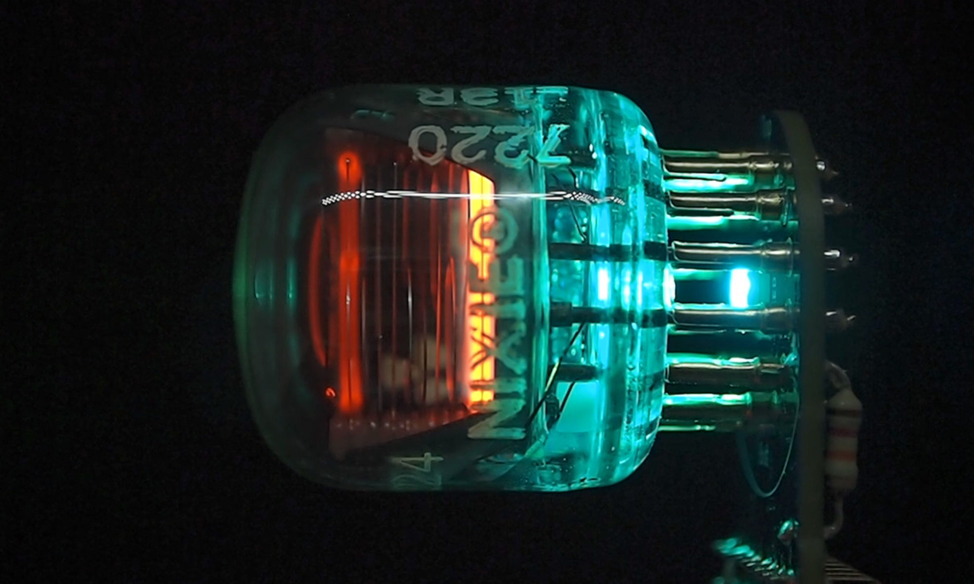
My preferred Bluetooth module is the KRC-86B, pictured below:
KRC-86B Bluetooth Module
There are a lot of possible connections that we aren’t going to use. We are just going to provide it with a Vcc of +5V and use OUTL and OUTR like so:
KRC-86B Connections
The LED indicates the state of the module. If it is connected it will be steady. If it is not connected it will be flashing, and if there is no power, it will be off! The capacitor is just a decoupling capacitor. Both of these are normally provided with the module.
Power Supply Details
The KRC-86B needs 3.7V to 5V. You could provide this with a battery pack or an external 5V supply and you could wire this power source in to the switch so that it only powered the module when it was selected as an input, but you would need a three-pole double-throw switch to do that.
The module only draws at most 80mA, so let’s see if we can provide that directly from the radio. We will probably need to convert some AC voltage into a DC voltage. Some radios have a transformer that provides the filament voltage, and these are probably the cleanest way to power the device. We can just convert the 6.3V AC into 5V DC. Another alternative I have used is to connect my power supply in parallel with the filament of a vacuum tube.
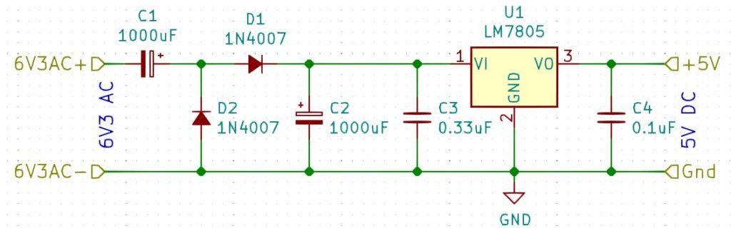
The basic idea is to rectify the AC, smooth it and then feed this through a 5V voltage regulator. 8V-12V is ideal for using a bridge rectifier, however 6.3V won’t provide a high enough rectified and smoothed voltage to feed a 5V voltage regulator, so in this case we need to use a voltage doubler as in the circuit below:
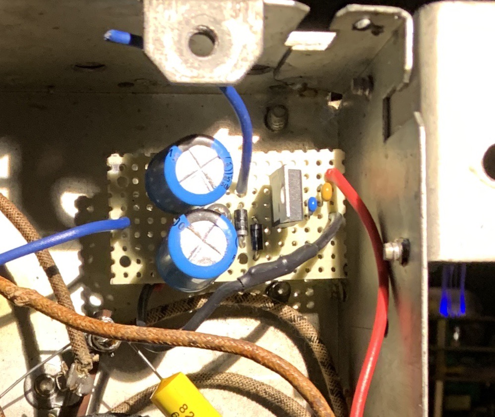
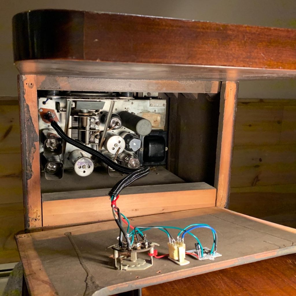
Here’s what it looks like. In this case, there was a handy post I can screw it to:
5V DC Power Supply
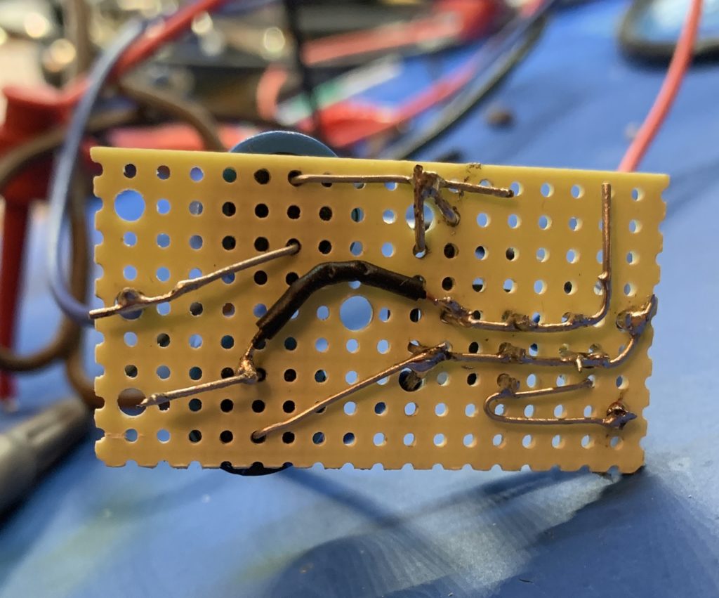
This is what it looks like underneath:
Some nifty point-to-point wiring
Finally, here is what the module, switch and auto-transformer look like in one of the radios I modded. In this case the switch was already there from a mod that had been made in the dim and distant past:
Bluetooth mod installed in a Philco 38-7 chairside radio
I have made several nixie clocks built around the ESP32. They incorporate a speaker, and I thought it would be nice if I could also stream music to them. The ESP32 has built-in Bluetooth support, so I figured I should try and use that first – essentially turn the clocks into a Bluetooth speaker.
I set about looking for examples and rapidly discovered that this was a little-used feature. Almost all the coding examples on the internet focus on Bluetooth BLE. I needed to use Bluetooth A2DP. Furthermore, I needed to implement an A2DP sink – that is something that audio data is sent to rather than from.
All of the code I could find was very low level and hard to understand – it would have been hard to incorporate it into an existing code base. It was all written in C, had zero encapsulation and seemed to be littered with code that was unnecessary for what I was trying to achieve.
To cut a long story short I wrapped it all in to some C++ classes. There are four main classes:
Audio
DataSink
EventSink
Out
Audio
This class just initializes the bluetooth protocol stack.
DataSink
This class listens for audio data and writes it to a ring buffer.
EventSink
This class listens for A2DP lifecycle events such as connected, suspended, configure etc. and publishes the events to any objects that subscribed to them.
Out
This class reads the audio data from the ring buffer and streams it out to an external DAC connected to the I2S ports.
The code is here. It can be used with or without the ESP32 Arduino framework. There is an example that uses the Arduino framework in the repo.
In the end I’m not using it with my clocks. All the code together blows the heap allocation and requires me to use a different memory layout. I might look in to sorting that out later.
This is the fifth post about a nixie clock project that is powered by a vacuum tube power supply, rather than the more common 12V or 5V wall wart.
After part 3, I took a brief detour to talk about the controller hardware, and I had left off talking about the lack of a 5V supply. I had originally hoped to power everything from the mains transformer, but my choice of vacuum tubes made that impossible, because they pulled the 5V and 6V3 supplies up to a high potential, and my circuitry needs to share a 0V rail with the HV supply.
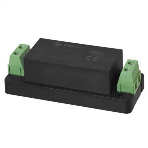
The other aspect of all of this, that I hadn’t managed to resolve, was that I wanted to be able to turn off the HV from the control circuitry. I had mulled over just severing the input the rectifiers (because I wanted to keep the 6V3 winding alive for the 5V DC rail), but now that I couldn’t use that anyway, the problem was solved. I would just use a separate 5V supply and use a SSR (Solid State Relay) to control the mains input to the transformer. I went with a fully enclosed chassis mount 5V supply from CUI.
CUI PSK-S6C-5-T
One final thing I added was a varistor across the input to protect against voltage spikes. One thing I wish I had added, but didn’t, was an inrush current suppressor.
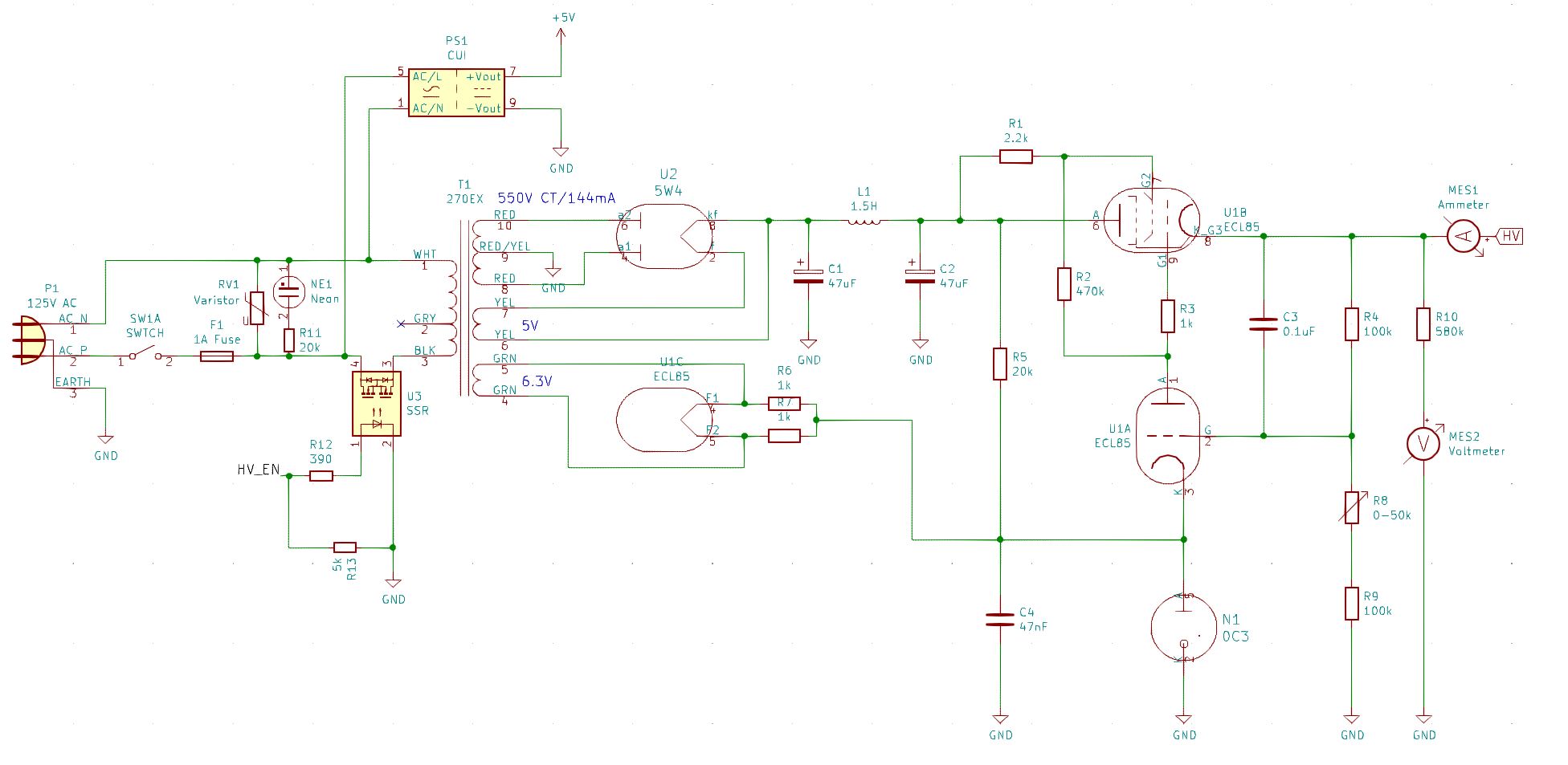
So anyway, this is the final final circuit:
Final Final Power Supply
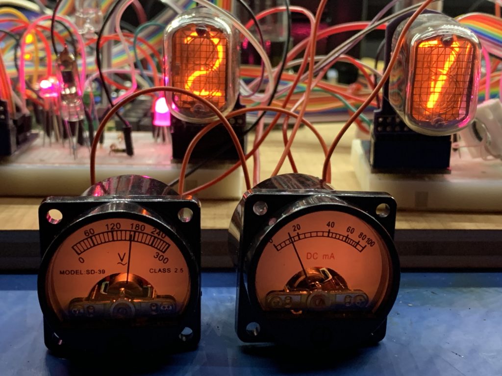
You’ll notice that this circuit includes a voltmeter and an ammeter. I had originally intended to add a voltage/current display using CD13 nixie tubes, which are very small, but I decided this was a step too far. In the end I went for a couple of analog meters because I could put them in the high side, unlike digital meters. I felt that they also matched the aesthetics better than digital meters would. They aren’t just for show. I wanted a simple way of monitoring the voltage and current over time so it would be more obvious if things were starting to drift.
Voltage and Current Meters
You might notice that the voltmeter is for AC (the ~ symbol under the V). I took one of these apart to see what was inside, and it is just a diode to rectify the voltage, so it would be fine with DC too, but I would have to add a resistor in series to re-calibrate it for DC.
These were the smallest, old-style meters I could find, and they included the internal illumination. I drove the bulbs off the 6V3 circuit, so they are a little dim, but that is OK by me.
This is the fourth post about a nixie clock project that is powered by a vacuum tube power supply, rather than the more common 12V or 5V wall wart. The previous part can be found here. I’m going to take a break from talking about the power supply and veer off into talking about the controller hardware.
One of the features I had wanted to add to a nixie clock for some time was to simulate the ticking noise of a mechanical clock. To that end, I had previously bought an ESP32 Pico dev kit (because it support I2S), but then done nothing with it. It was time to resurrect that idea. By the way, the reason for choosing the Pico was that the chip itself requires the minimum of additional hardware to build my own PCB using the chip.
Now that I was seriously developing for the ESP32, I actually delved deeper into the software platform and discovered that it is running RTOS. This is a real time operating system with support for multiple prioritized tasks. In fact, the ESP32 arduino platform uses a single RTOS task to implement the loop() callback. My code for the ESP8266 basically split the work in the loop() method into multiple tasks, so I figured I could drop all the scaffolding I had written to do that, and just use one RTOS task on the ESP32 for each task that I wanted the ESP32 to complete (the clue is in the name!), rather than stuffing a bunch of calls into the loop() method.
The first thing I wanted to play with was playing sounds – that was the whole point of considering the ESP32 for the core processing. I started by looking around for libraries that I could use to play sounds and settled on ESP8266Audio which, despite the name, has good support for the ESP32. For it to be useful, I also needed to buy a SD Card reader module and an I2S amplifier module, both of which are available from Adafruit.
One advantage of the ESP8266Audio library is that it uses DMA to feed the data to the I2S pins of the ESP32. So theoretically, user code just has to keep the DMA buffer full, and then the data is pushed out of the pins via interrupts. It seemed like this would be the right thing to do as I was going to be loading up the processing to handle more and more tasks. I initially had trouble with the sound glitching. It was difficult to tell if this was because of the software or the breadboarding I was doing. As I added more tasks the glitching got worse. In the end it was easily fixed by increasing the DMA buffer count from 8 to 64!
The next task I wanted to add was driving neopixels. I had tried this before on the ESP32 with little success. It tended to be very glitchy. Looking around I discovered another library called NeoPixelBus which, like ESP8266Audio, could use DMA to feed data to the NeoPixels. Fortunately there are two DMA channels on the ESP32 and also fortunately, I could tell the libraries which one I wanted them to use. However, the neopixels would still occasionally glitch. At this point I wasn’t sure if this was because of my breadboarding or the software, so I chose to ignore it. It turns out that there is a bug in the ESP32 DMA firmware. NeoPixelBus changed their default support to use the IR remote support, but I still found that it glitched occasionally. Finally, when I upgraded the Arduino platform to v1.0.4, the glitching stopped.
Next I needed to drive the Nixie tubes. I implement fading and cross fading all in software, so I need better timer resolution than can be provided by the task manager. So I implemented this in an interrupt routine. I had already done this for the ESP8266, so I was familiar with the need to decorate all interrupt methods so that they would reside in IRAM. However it turns out that that wasn’t enough.
Firstly, my interrupt code is in C++ and uses virtual functions. It turns out that for the ESP32, the compiler is putting the v-tables in flash, so I had to resort to copy/paste and get rid of all of the virtual functions. BTW, the version of the ESP8266 platform I was using was storing the v-tables on the heap. Later versions allow you to specify where the v-tables are stored. It would be nice if the ESP32 platform did the same.
It still crashed, and I eventually discovered that g++ was generating function calls to do long division. That function is not in IRAM. The millis() function (which is in IRAM) uses long division. I guess no one had ever called it from an interrupt routine before? Thankfully the developers changed the default compiler flags to inline the code instead. So all was good.
Next I wanted to use a WiFi manager library to handle setting up the connection to a router. Thankfully, the one I prefer to use – ASyncWiFiManager was also the only one that had been ported to the ESP32. However, my iPhone simply would not connect to the access point – my laptop had no problem. Turns out that there was a bug in the ESP32 core which was fixed just after I discovered the issue. An aside: this is interesting, I am pretty sure the ESP8266 core has a similar problem, as connecting to the AP from an iPhone is patchy on the ESP8266.
So then I was implementing my Web GUI, which uses the SPIFFS library to store the assets. That’s when I discovered that the SPIFFs library on ESP32 was broken. So I fixed that and the fix was incorporated into the Arduino core.
So finally, everything that I needed (software wise) worked great and has, in fact, been extremely stable.
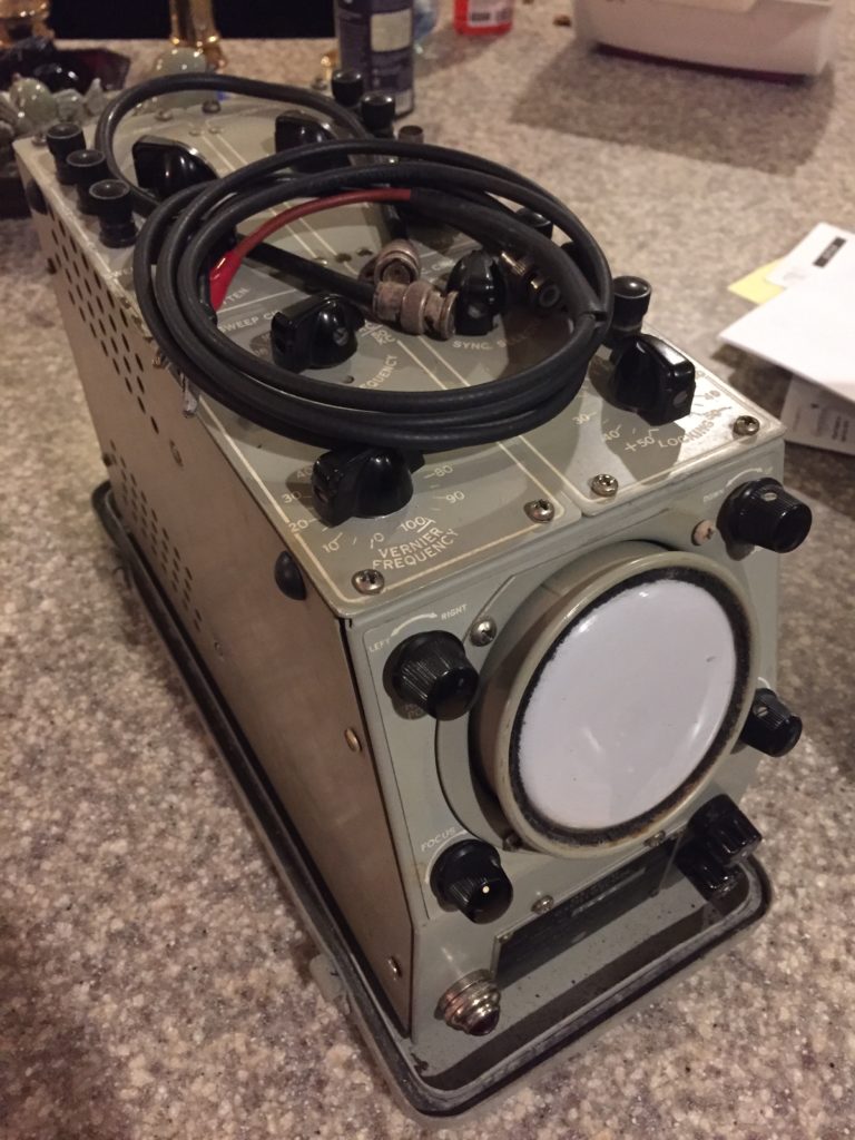
While I was developing hardware for Nixie clocks/fixing radios etc., I had a hard time finding some specific tools, so this is to save you the angst. I’m not going to cover the basics like oscilloscopes, isolated power supplies, variacs, heat guns and soldering irons. Most forums will recommend stuff. One thing: if you get an oscilloscope, don’t buy a new one of those small portable chinese jobs – get a good used one like an old Tektronix.
Missing from this list (because I haven’t bought them yet) is a signal generator (a FY6800) and a network analyzer (a NanoVNA).
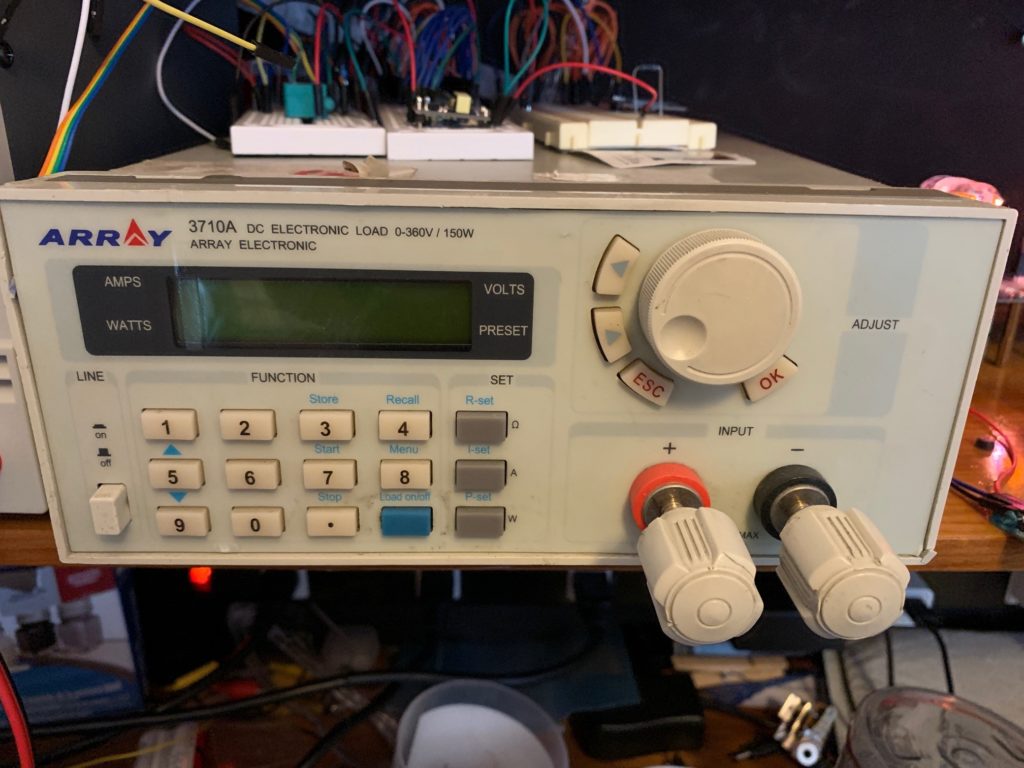
Electronic Load
First up is an electronic load for testing HV power supplies. Most affordable electronic loads are built to test battery chargers, so although they will go to a high current, they can’t handle the voltages. You need a 3710A – pick one up on eBay.
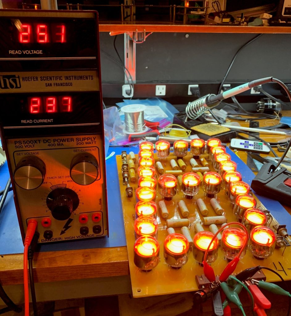
Bench Power Supply
Again, affordable units can’t provide the kind of voltages needed by Nixie tubes, let alone Dekatrons. Get a HSI PS500XT. Fare warning, this is a lot of power – use at your own risk! This will power every Nixie tube you own at the same time. Or one of these IN-28 displays (that’s 250V, 237mA):
You will need a regular bench power supply too – one with a bit more finesse!
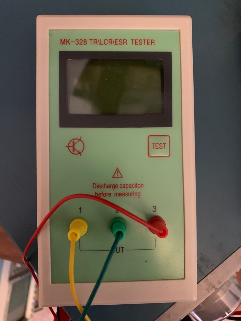
LRC Tester
So you’ve got a bunch of discretes lying around – resistors, capacitors, inductors, transformers, transistors etc. etc. What do you test them with? Get a MK-328. A truly remarkable device at a ridiculously low price.
So I had a functioning prototype (see the end of Part 2), but at about this time I bought an old oscilloscope:
Old Oscilloscope
So I started looking around for oscilloscope clock kits and eventually I hit this site (which is an overall fascinating site). That site had a page that introduced me to voltage regulator (VR) tubes. He was using two tubes called 150C2 (aka 0A2) to provide +150V and +300V. Now the great thing about VR tubes (for me) is that they are also cold-cathode tubes – i.e. they contain some mixture of noble gasses, and they glow. It looked like I could easily produce a regulated power supply using these tubes, but of course there was a catch – or several in fact:
These are like nixies or any other neon tube – they need to be current-limited. The 0A2 will take a maximum current of 30mA. The way that Grahame was using them was to tap off the required voltage after the current-limiting resistor. So that resistor had to be sized to allow the minimum required current for the VR tube (5mA in the case of the 0A2) + the maximum current for the nixie tubes. I was planning on drawing around 50mA, so I would need a resistor that limited the current to 55mA. However when all the nixie tubes are off, that would mean the 55mA would be flowing through the VR tube, which exceeds its maximum by 25mA. I suppose I could have used several in parallel, perhaps even one VR tube for each nixie tube! However there is the second issue:
The regulated voltage that they establish is, at the most, 150V (different VR models have different maintenance voltages). Again, I could use two in series, but now we are getting a little ridiculous.
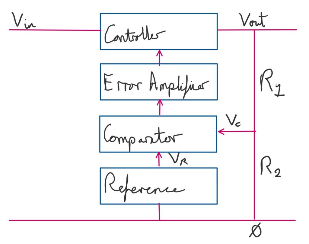
It was time to do some more research. The solution is to use the VR tube to produce a reference voltage and then construct a feedback loop that measures the difference between this voltage and the desired output voltage and adjusts the output to stay at the desired level. At a high level, it looks like this:
Regulator block diagram
Together, the system tries to keep Vc equal to Vr, and therefore Vout constant, no matter what happens to Vin. Though there are limits to how much variation it can handle. In this system
And since Vc = Vr
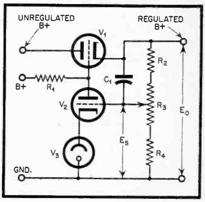
We have the reference voltage – it is a VR tube. What about the other three? The comparator and error amplifier are one device – in this case a triode. The controller (usually called the series pass tube, or just the pass tube, in this toplogy) could also be a triode. This diagram, from a 1947 issue of Radio magazine, illustrates the components nicely, leaving out various supporting resistors and capacitors:
High-level regulated power supply design
However, I will use a pentode for the pass tube, because I’m going to use a single tube that contains both a triode and a pentode – the ECL85 (aka 6GV8). The VR tube will be a 0C3, because it is a 108V VR tube and it looks nice!
As it turns out, the ECL85 also has a 6V3 heater, but it needs it to be at a potential that is within 100V of either cathode. That means I can’t use the same 6V3 transformer winding for both the ECL85 and the rectifier tube. In addition, there is significant voltage drop across the pentode and the whole thing will need more current to drive it, so it was time to look for both a new transformer and a new rectifier tube. I ended up going with the 5W4G, which still has a reasonable forward voltage drop and can handle the additional voltage and current. In addition it has a 5V heater which works well in this setup, because transformers that have one 5V and one 6V3 winding are more common than transformers that have two 6V3 windings. For the transformer, I settled on another Hammond, the 270EX.
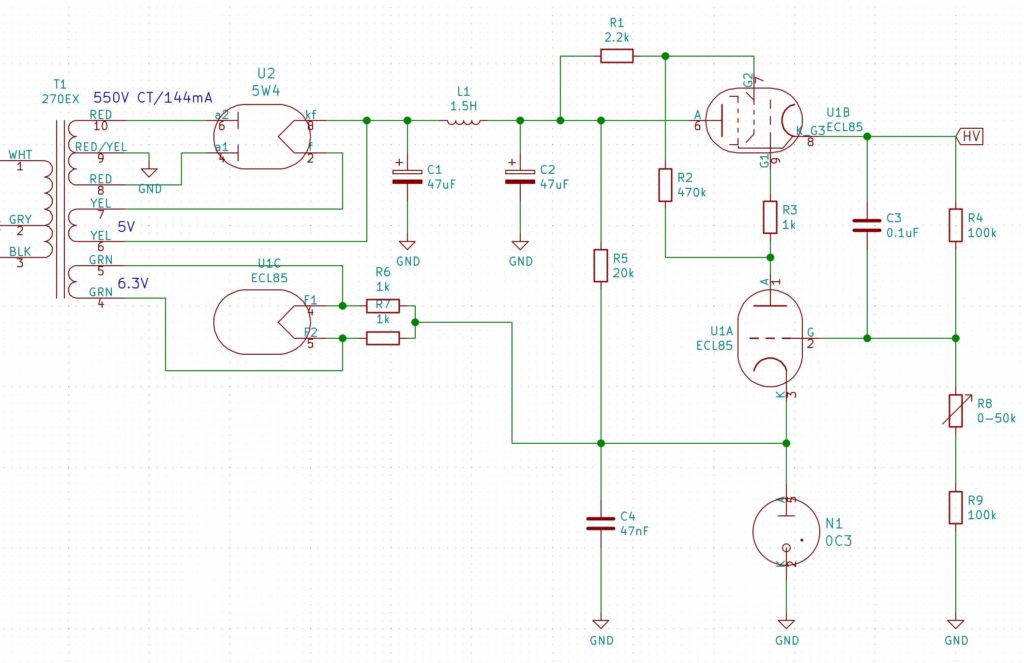
The 5W4G has a directly heated cathode, unlike the 6CA4, which means that it is at the same potential as the cathode. So now I have a problem. Both the 5V and the 6V3 windings are at different potentials than the main secondary winding, which means I can’t use either of them for my 5V supply, at least directly, as my 5V supply needs to share a 0V rail with the main secondary. I’ll come back to this later – I want to talk about the control circuitry first. I’ll finish this post with the final circuit diagram of the power supply:
In Part 1 I covered the genesis of this project and my first stab at a vacuum tube power supply.
One of the things I wanted to do was provide all of the power for the clock from the transformer. My regular clock circuit only needs 5V, so I figured I could get this from the 6V3 filament winding using a bridge rectifier and a 5V voltage regulator. This is only really possible because the 6CA4 rectifier tube uses an indirectly heated cathode. That is to say, the heater is not connected to the output pins, so it can be at any potential with respect to the output voltage. In particular, it means we can tie one side of the heater to the common ‘ground’ or 0V rail. The HV ‘ground’ is the center tap of the secondary:
Circuit, showing heater
Some of you may have figured that that is cutting it a bit too fine. A bridge rectifier using regular diodes could drop around 1.4V to 2V depending on the current draw. The voltage regulator would drop another 2V, so it needs a steady 7V in. So if the smoothing were perfectly efficient, we would go from 8.9V (6.3*1.414) to possibly less than 7V. Simulation with LTSpice shows this is optimistic.
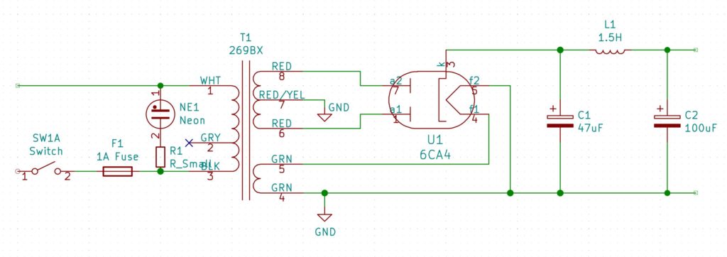
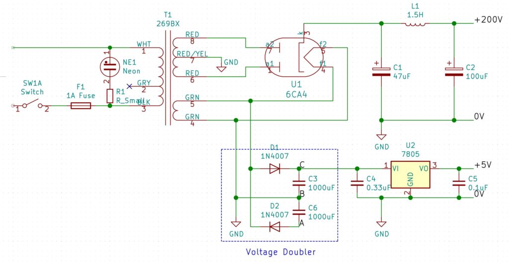
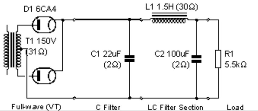
Another alternative would be to use Schottky diodes for the bridge, and simulation show this would probably work. However, I decided to use a simple voltage multiplier on the 6V3 AC which gives me better smoothing for fewer components. So the whole circuit now looks like this:
Circuit with 5V section
You’ll note that this diagram is slightly different. I have cut the direct connection between pin 4 of T1 and the 0V rail of the HV section. Instead I have explicitly shown each section (the voltage doubler, HV and 5V sections) with a separate connection to ground. This is because, as it is, I am only using one half of the voltage doubler. This is just one diode drop, rather than two (as with the a full-wave bridge), so the voltage is enough for the 7805 regulator. If I wanted to use the full doubled voltage, I could just move the voltage-doubler ground to the point labelled A instead.
This is all very well, but it turns out to have a couple of draw-backs, as will become apparent later.
Current Limiter
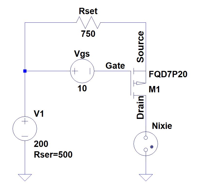
The HV power supply is unregulated – which is to say, as you draw more current, the voltage starts to sag. This is because the forward voltage drop of a rectifier tube increases as the current increases. To get around this I decided I would use a small constant-current circuit to drive my Nixie tubes, in place of the usual current-limiting resistor. This basically works by connecting the source of a PMOS transistor to HV via a resistor (Rset) and then biasing the gate a fixed voltage below HV (Vgs) like so:
This is the equation for the resistor, given the desired current (Id):
Where Vgs(on) is the voltage drop between the source and the gate, which you can get from the transfer characteristics chart of the data sheet. A rough estimate would the typical gate threshold voltage.
Of course, the trick is to keep Vgs constant, even though HV is varying. To this end, I used a small isolated DC-DC converter to boost 5V to 12V and then attach it to the circuit as shown above. The gate takes virtually no current, so the boost converter can be very small. Using a voltage divider let’s us get to 10V and using a small potentiometer in one leg of the voltage divider allows us to adjust the voltage to get precisely the current we want.
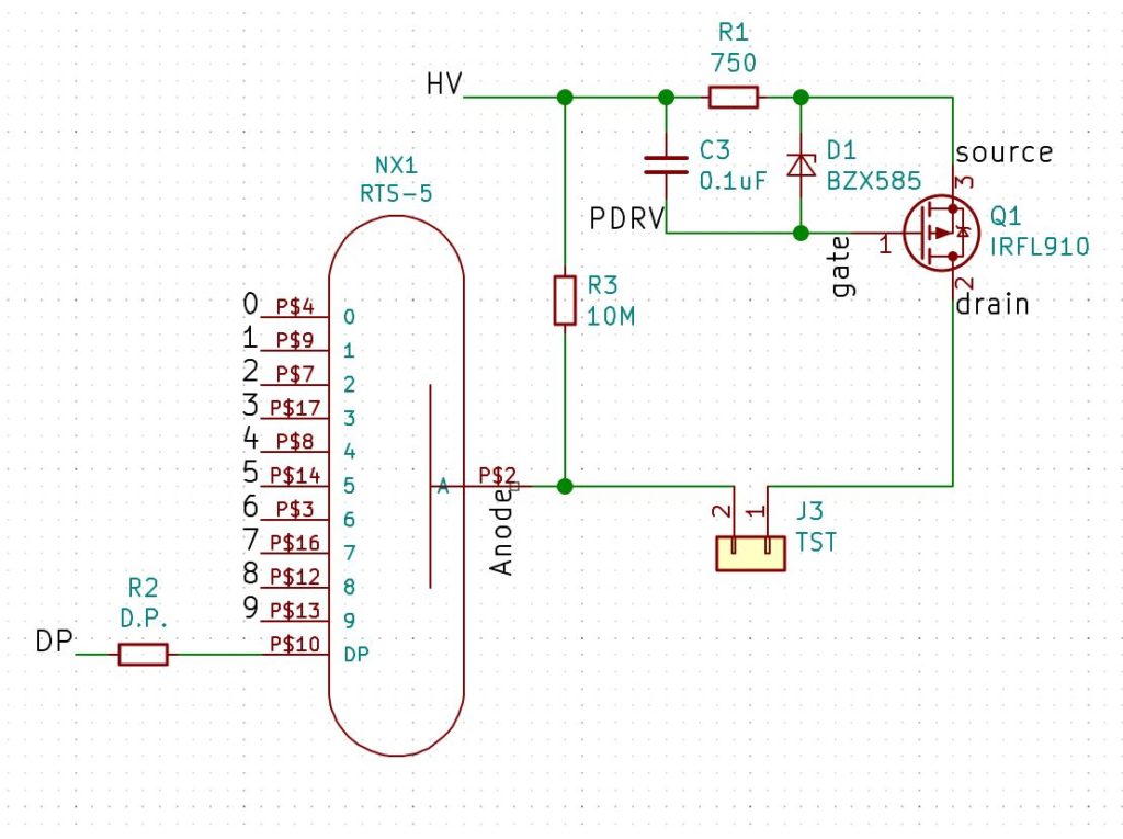
Following some advice I received on the Neonixie google group, the actual circuit is a little more complicated, to provide some protection to the MOSFET. I designed some boards to act as sockets for the nixie tubes that included all this circuitry:
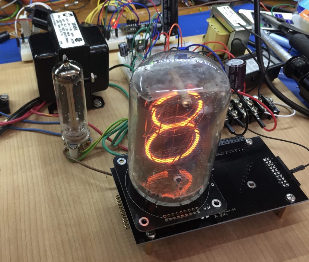
At this point I had decided I would ultimately want to use all of this to build a clock that would feature the large NL7037 tubes I had been collecting. I had been meaning to build a clock with an industrial feel to it to match the look of these tubes, and I felt that this would be the one. Finally here is a shot of a test I made using one of the tubes and adapters:
About 7 months ago, I watched a video by glasslinger about adding a nixie tube display to a vintage radio. This was something I had wanted to do for a while, but I didn’t know how to read the tuned frequency from the radio. There were many interesting parts to the video (I recommend you watch it), but one of the things I learned was that vacuum tube radios that had tranformers, actually generated voltages with those transformers that were high enough to drive Nixies.
I spent a little while trying to find a radio with an input transformer like that, and in the meantime, I started researching vacuum tube power-supply design. That was when I finally realized that these things were still being made for guitar (and HiFi, but especially guitar) amplifiers. So you could actually buy new transformers and new vacuum tubes and new chokes that you could use in a new power supply. That is when I got really serious about this.
At this point, two sites influenced my initial design. The first was ‘Fun With Tubes’, which had several simple designs. The second was ‘DIY Audio Projects’. which went in to much greater depth about tube selection and circuit calculations. In particular, the latter had a nice chart showing the voltage drop that different vacuum rectifier tubes had. Some of them were quite startling – for example the 5Y3, used by the first site, had a voltage drop of almost 45 volts for a plate current of 100mA, compared with only 15V for the 6CA4. What’s more, the 6CA4 is still in production.
The DIY Audio projects site showed a long series of manual calculations to determine properties of that simple un-regulated power supply. I entered these in a spreadsheet to make life easier, however, I later found a little application called psud2 (power supply designer 2) that did the same thing using a simulator and a few values from the data sheets. The important thing being that the maximum 6CA4 plate current (which is on a cold start) does not exceed the maximum allowed plate current on the data sheet.
Taking a hint from the DIY Audio Projects page, I decided to go with a one-stage choke filter to smooth the output of the rectifier tube. Confusingly (for me) everyone refers to this as the ‘input filter’. I guess because it is the input to whatever comes after this stage – usually an amplifier. So this is what I ended up with (from dsud2):
Unregulated vacuum tube power supply
Obviously(?) this is just the output stage. On the input side is 125V 60Hz, a 1A slow blow fuse in the hot line and a neon indicator across hot and neutral, so I could tell when it was on.
Something I omitted was a resistor to drain the capacitors when power was removed. Those capacitors can hold a charge for a long time. I soon added one. Experience is wonderful thing.
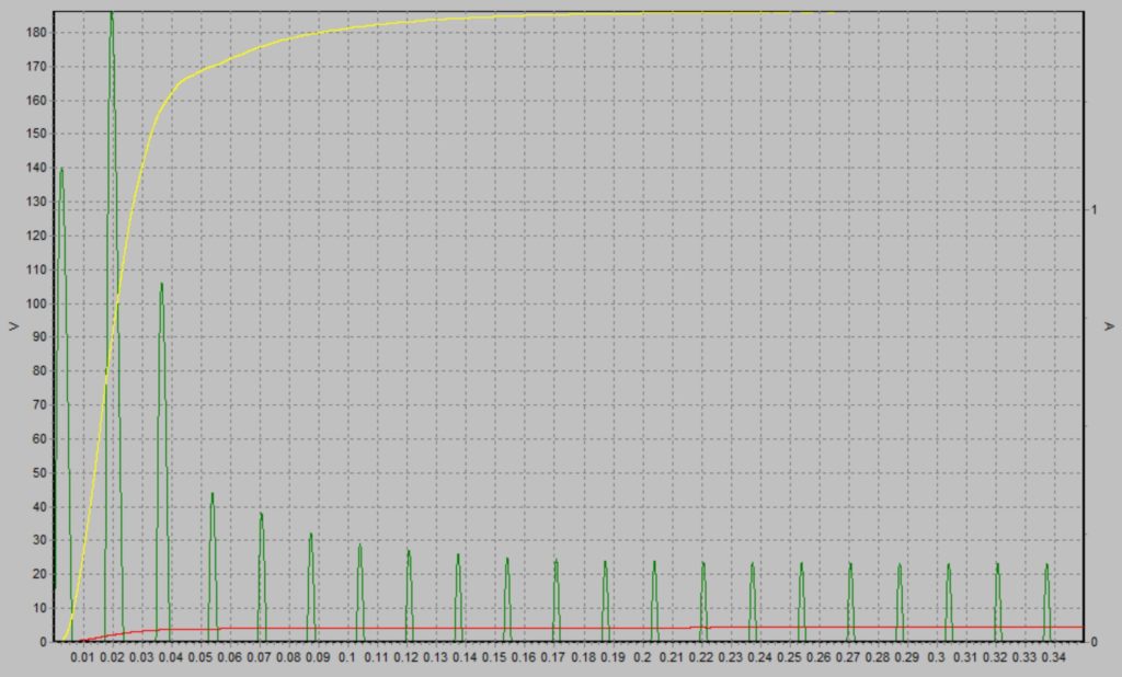
Here is a chart from psud2 showing the expected output:
Power supply simulation
The next stage was to select some actual components and bread-board it. I ended up going with a 269BX transformer from Hammond, a 156R choke (also from Hammond) and a new 6CA4 from JJ Electronics. All the rest are just suitably spec’d parts from DigiKey and a bunch of terminal strips, screws, fuses, switches, fuse holders etc. from my local electronics store.
I would show you a picture of the breadboard, but I will save that for part 2, when I discuss how to deal with the potential for voltage sag.
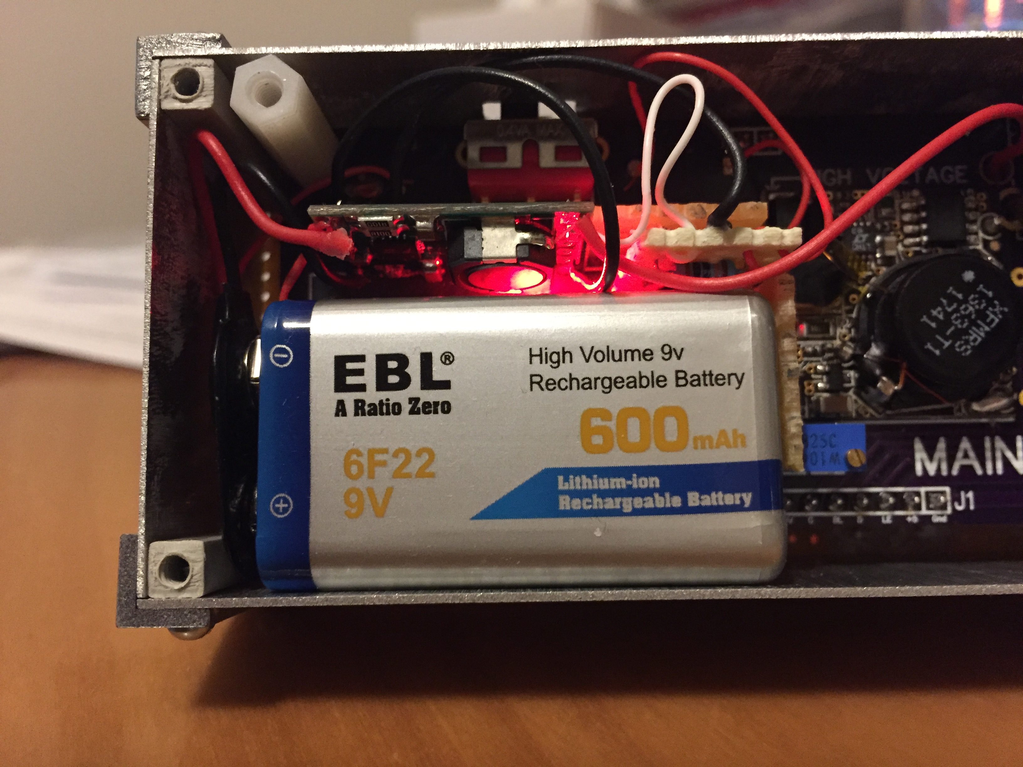
The divergence meter I built can be powered by an internal 9V battery. However, a regular 9V battery doesn’t last very long (between 10 and 45 minutes). LiPo 9V batteries last much longer – over 3 hours, though they aren’t really 9V as they are actually two regular LiPo batteries in series – so the actual voltage is at most 8V, dropping to 6V just before the power runs out.
However, that still means that you have to open the clock up to change the battery when it is out of power. A better alternative would be to include a power-sharing charger inside the case, so that the LiPo will charge up when the clock is plugged back into the power. A quick(ish) search of the internet turned up this 9V LiPo charger module, which is small enough to fit inside the case along with the battery. So that gave me the charger, but I needed to add the load-sharing part. A load-sharing charger will use some of the input power (input from the wall adapter) to charge up the battery, while the clock runs off the rest. It also needs to disconnect the battery from the clock as long as the clock is plugged in to the wall adapter, but instantly connect the battery to the clock as soon as it is unplugged from the wall adapter. This is actually pretty easy, and my circuit is basically the one described here.
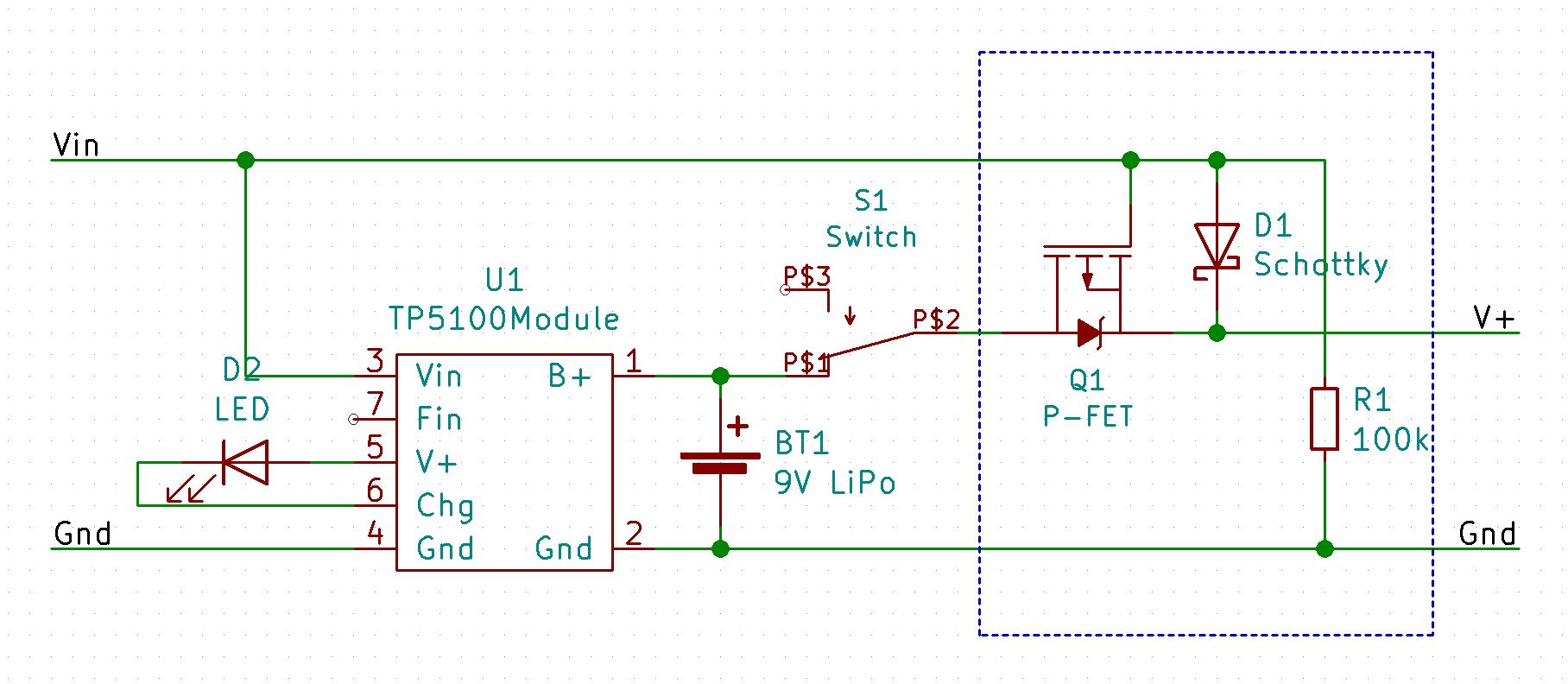
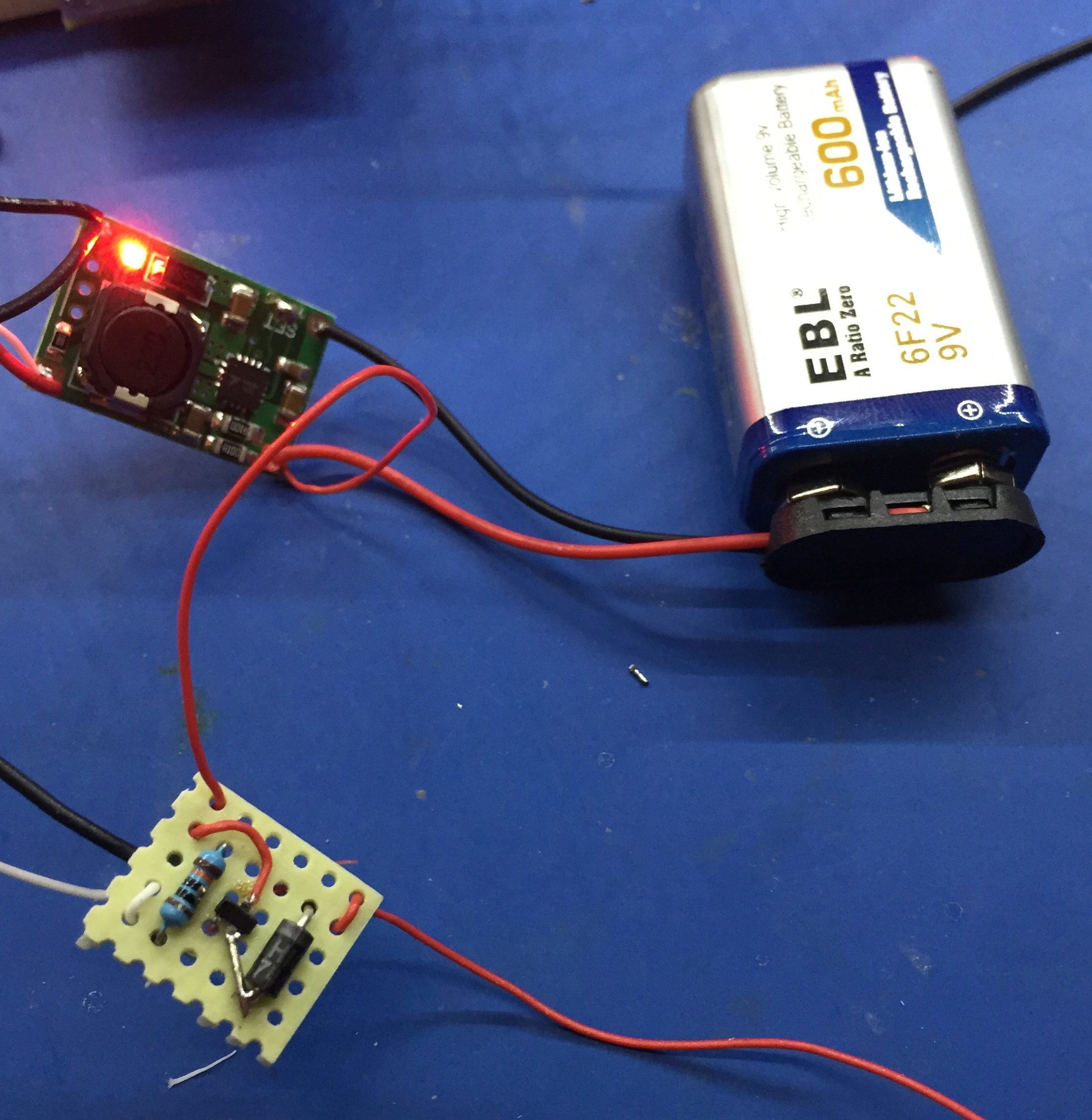
Here is the basic circuit:
Load Sharing Charger
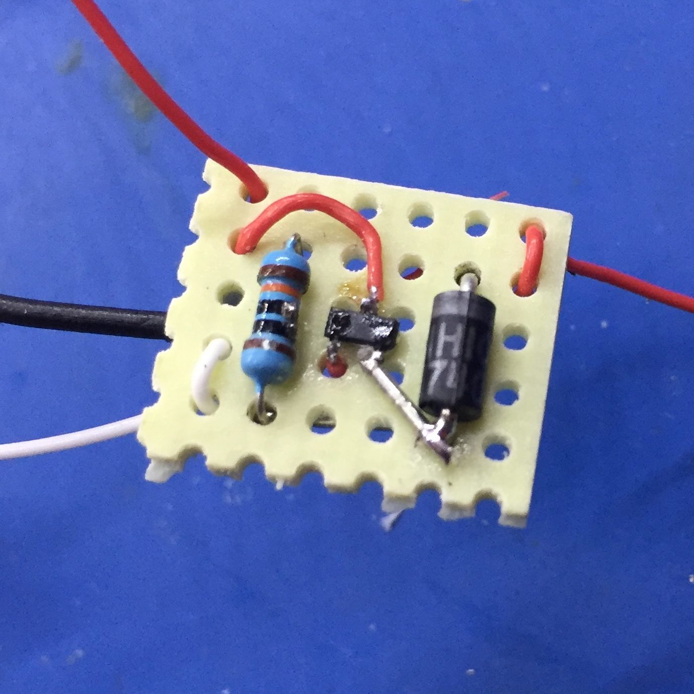
The load-sharing part is inside the dashed box. Here is what my implementation of this looks like. I used a surface-mount MOSFET, because I happened to have one already:
Load Sharer
This works as follows:
As long as there is power on Vin, the P-channel MOSFET (Q1) will be turned off, preventing any power from being discharged from the battery and also preventing any power from Vin being directly applied to the positive terminal of the battery. Power from Vin will flow to V+ through the Schottky diode (D1).
While there is power on Vin, the TP5100 module will also be able to charge the battery, if necessary.
As soon as power is removed from Vin, the 100K resistor (R1) will pull Vin to ground, which will turn on the MOSFET allowing current to flow from the battery to V+.
This is why the Schottky diode (D1) is needed. It stops the gate of the MOSFET being pulled high again by the battery, which would turn it off, etc. The only reason that D1 is a Schottky diode, is to minimize the voltage drop from Vin to V+.
The LED (D2) shows when the battery is being charged.
I checked it all out before stuffing it into the case:
Load Sharing Charger
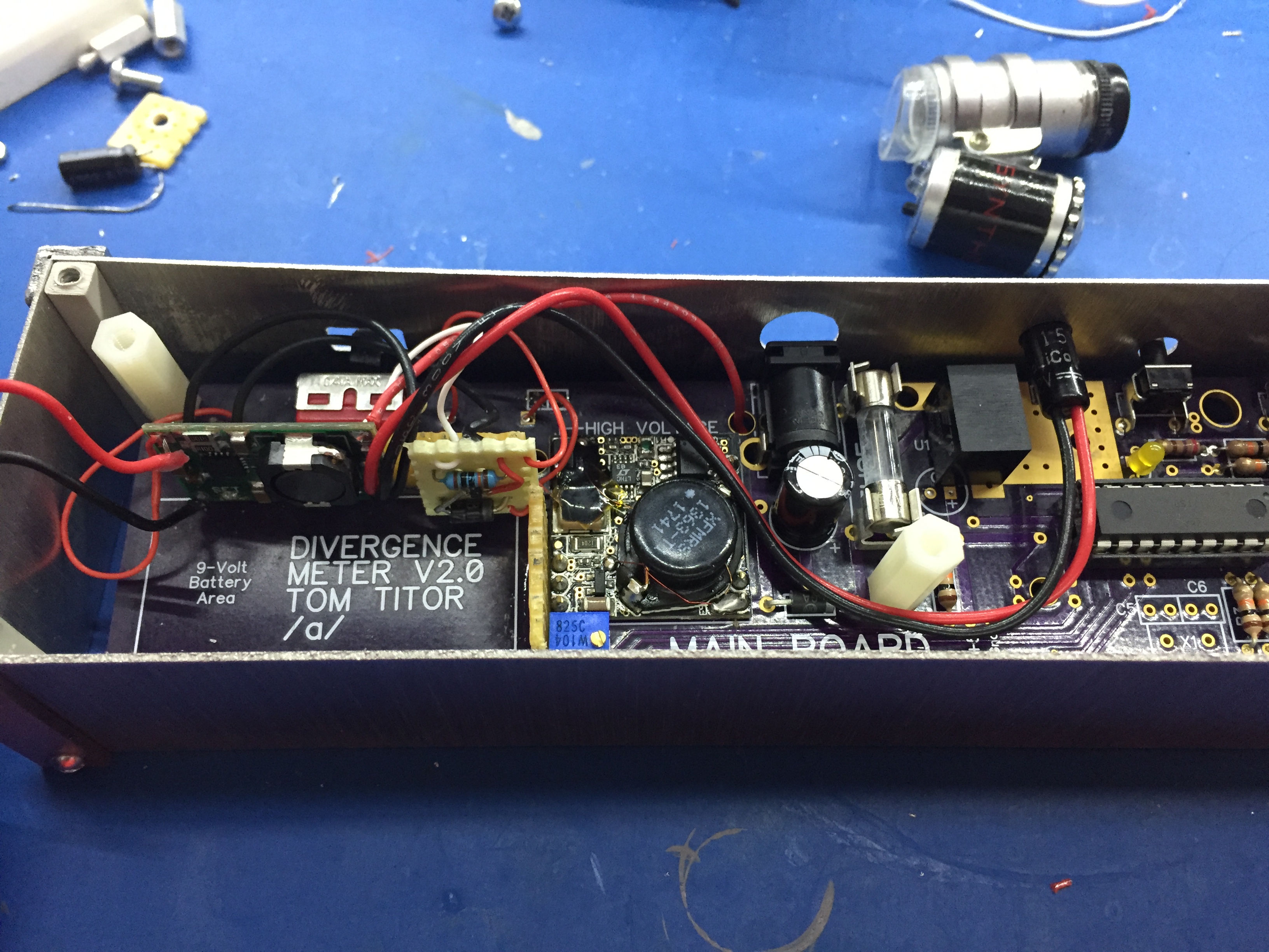
To integrate this with the clock, you have to cut the track from the Vin pin on the barrel connector (power in), then wire that to the Vin connector on the battery charger. Then wire V+ from the load-sharing board to the other side of the track that you cut – just find an easy place on the board to do that.
To re-use the existing switch, remove the optional diode (if you installed it) and just wire the switch up as shown in the circuit diagram above.
Finally, if you choose to use the charging indicator LED, you will have to drill a hole in the case somewhere to install it.
Here it is in the case:
Charger in the Case
View Showing LED Placement
I took a time-lapse video of the clock running off battery. As you can see, it lasts a little over three hours: