
The divergence meter I built can be powered by an internal 9V battery. However, a regular 9V battery doesn’t last very long (between 10 and 45 minutes). LiPo 9V batteries last much longer – over 3 hours, though they aren’t really 9V as they are actually two regular LiPo batteries in series – so the actual voltage is at most 8V, dropping to 6V just before the power runs out.
However, that still means that you have to open the clock up to change the battery when it is out of power. A better alternative would be to include a power-sharing charger inside the case, so that the LiPo will charge up when the clock is plugged back into the power. A quick(ish) search of the internet turned up this 9V LiPo charger module, which is small enough to fit inside the case along with the battery. So that gave me the charger, but I needed to add the load-sharing part. A load-sharing charger will use some of the input power (input from the wall adapter) to charge up the battery, while the clock runs off the rest. It also needs to disconnect the battery from the clock as long as the clock is plugged in to the wall adapter, but instantly connect the battery to the clock as soon as it is unplugged from the wall adapter. This is actually pretty easy, and my circuit is basically the one described here.
Here is the basic circuit:
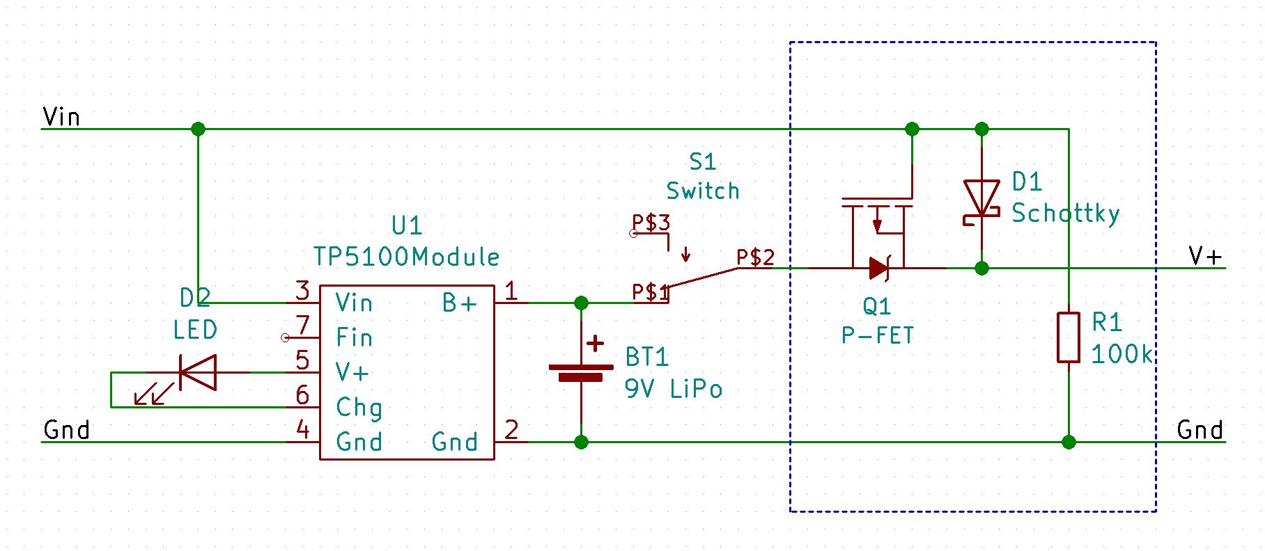
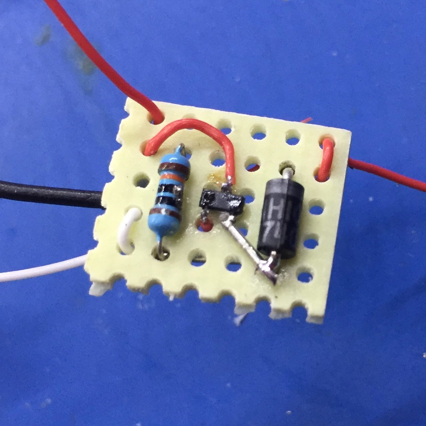
The load-sharing part is inside the dashed box. Here is what my implementation of this looks like. I used a surface-mount MOSFET, because I happened to have one already:
This works as follows:
- As long as there is power on Vin, the P-channel MOSFET (Q1) will be turned off, preventing any power from being discharged from the battery and also preventing any power from Vin being directly applied to the positive terminal of the battery. Power from Vin will flow to V+ through the Schottky diode (D1).
- While there is power on Vin, the TP5100 module will also be able to charge the battery, if necessary.
- As soon as power is removed from Vin, the 100K resistor (R1) will pull Vin to ground, which will turn on the MOSFET allowing current to flow from the battery to V+.
- This is why the Schottky diode (D1) is needed. It stops the gate of the MOSFET being pulled high again by the battery, which would turn it off, etc. The only reason that D1 is a Schottky diode, is to minimize the voltage drop from Vin to V+.
- The LED (D2) shows when the battery is being charged.
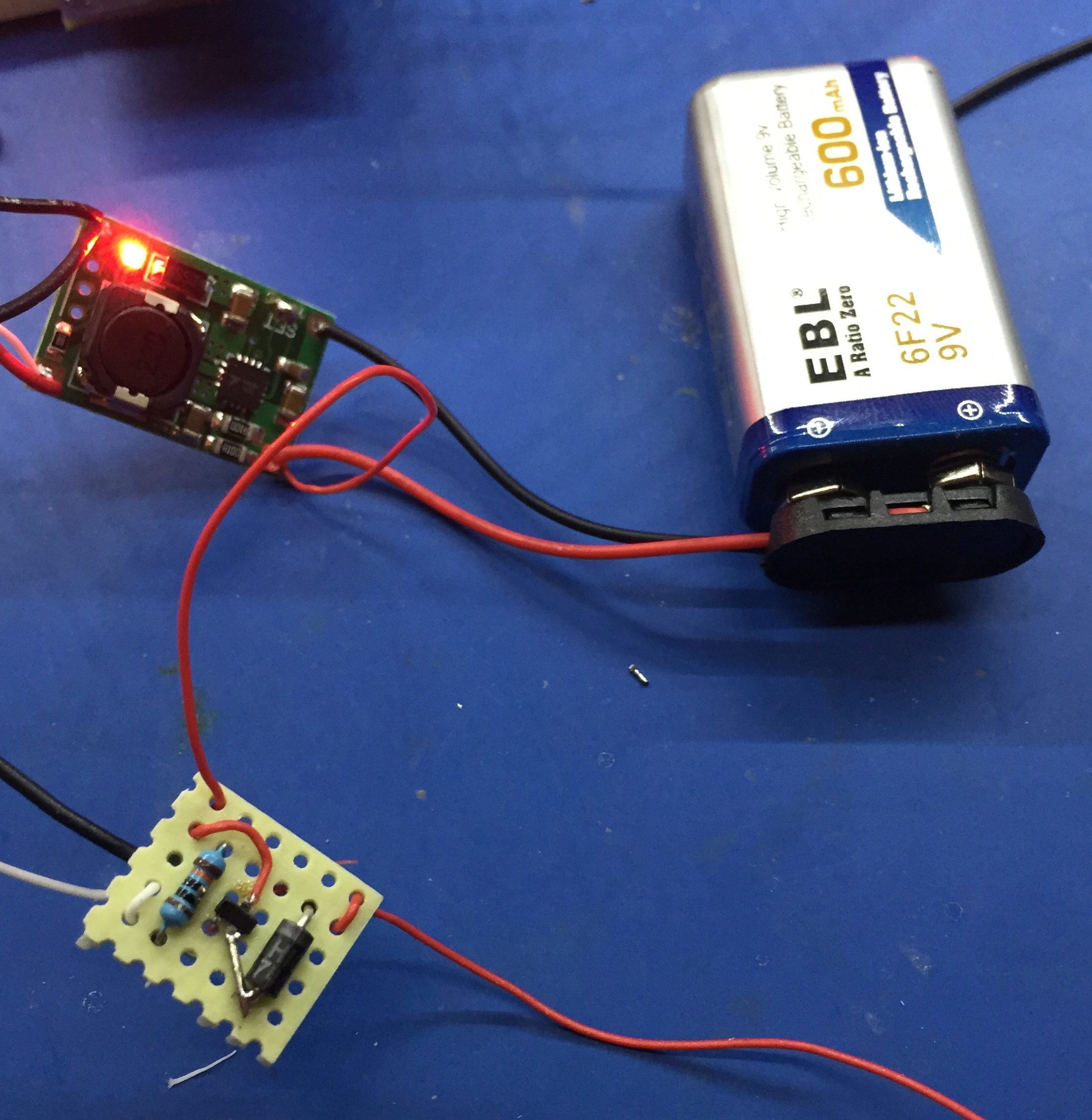
I checked it all out before stuffing it into the case:
To integrate this with the clock, you have to cut the track from the Vin pin on the barrel connector (power in), then wire that to the Vin connector on the battery charger. Then wire V+ from the load-sharing board to the other side of the track that you cut – just find an easy place on the board to do that.
To re-use the existing switch, remove the optional diode (if you installed it) and just wire the switch up as shown in the circuit diagram above.
Finally, if you choose to use the charging indicator LED, you will have to drill a hole in the case somewhere to install it.
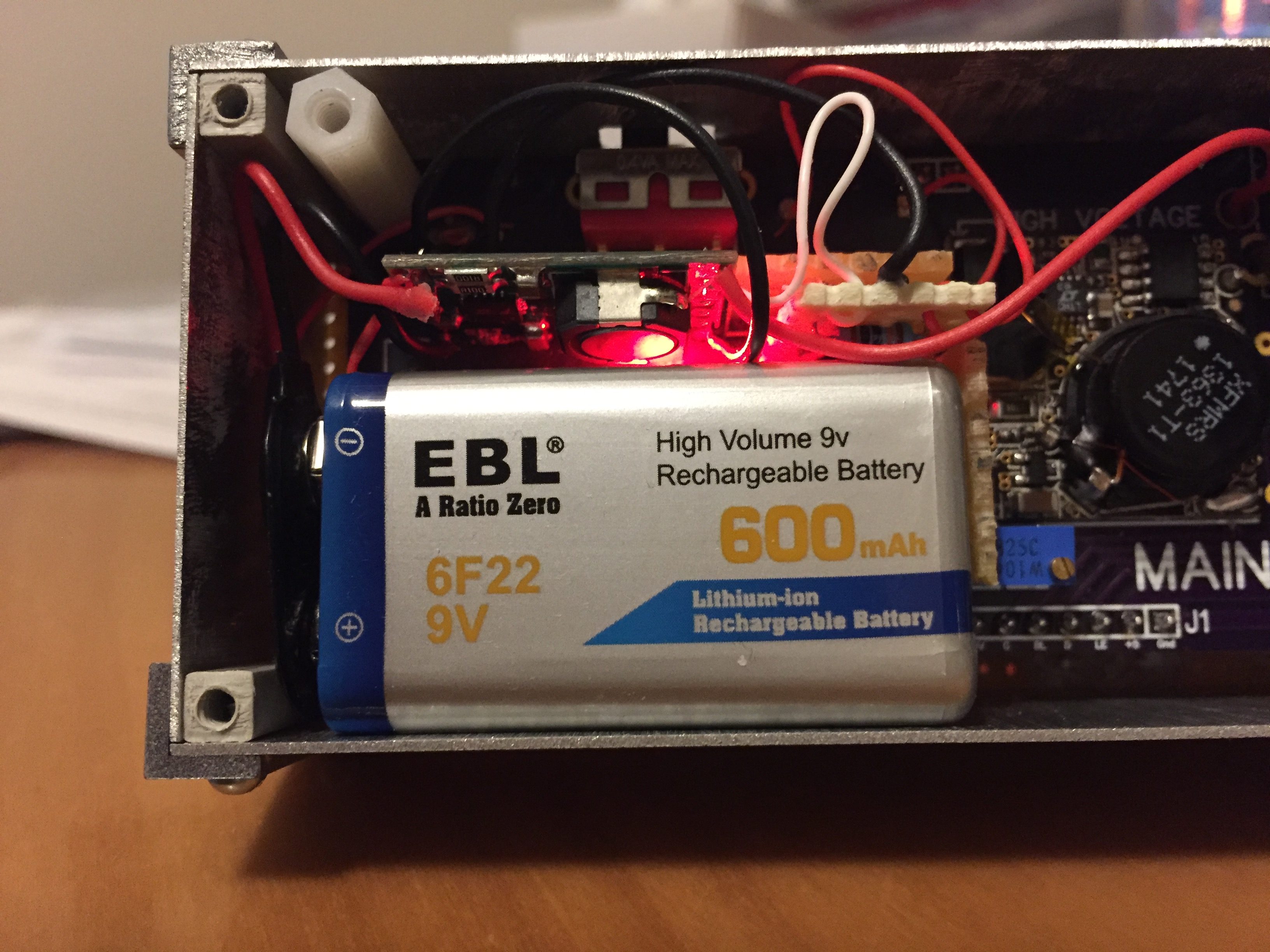
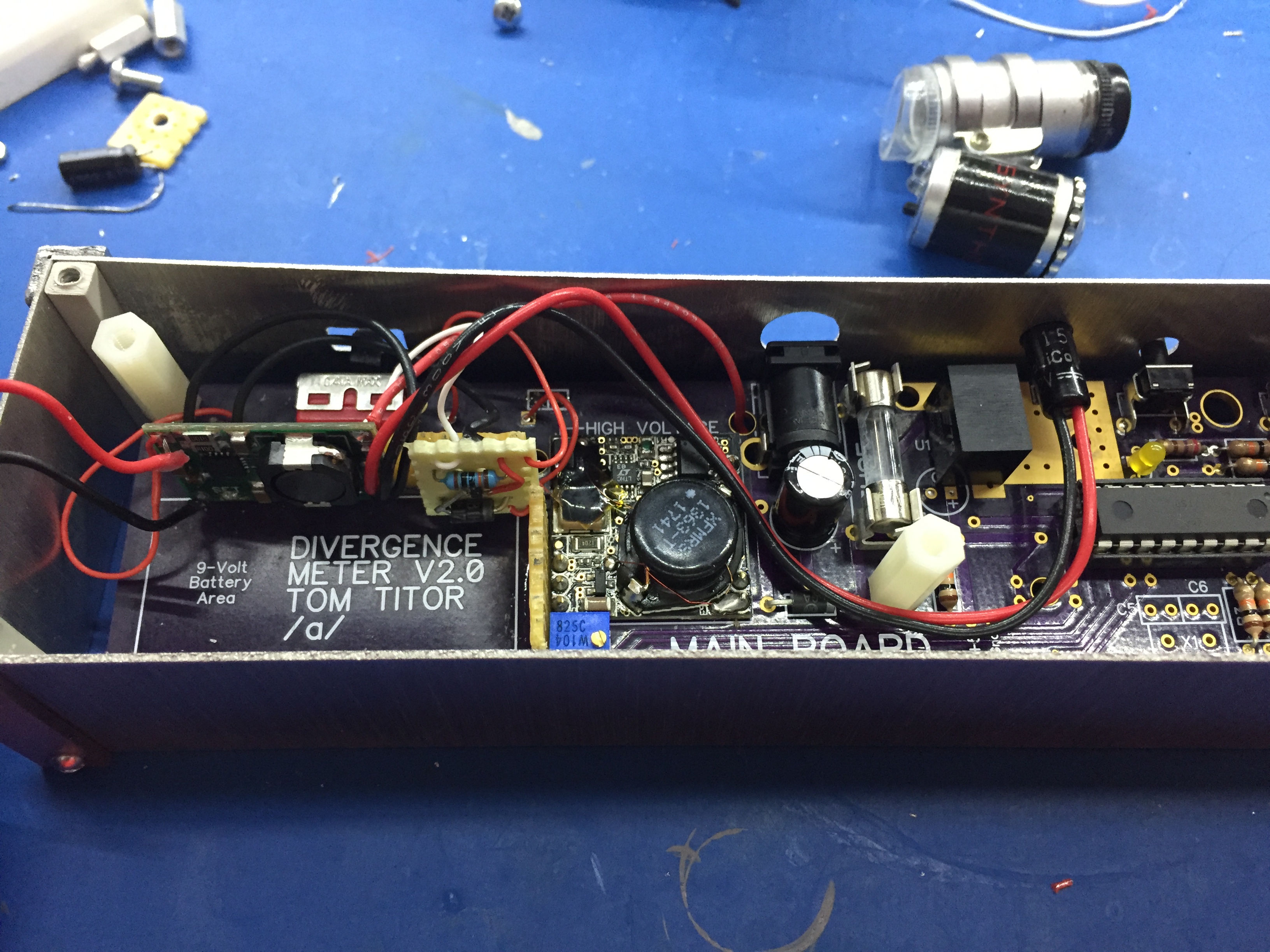
Here it is in the case:
I took a time-lapse video of the clock running off battery. As you can see, it lasts a little over three hours: